AUTEC - Dynamic Plus series
Light and acoustic warning signals 15
LIUDJR000_eng-00
7 Light and acoustic warning signals
7.1 Light signals
B
A
B A
C
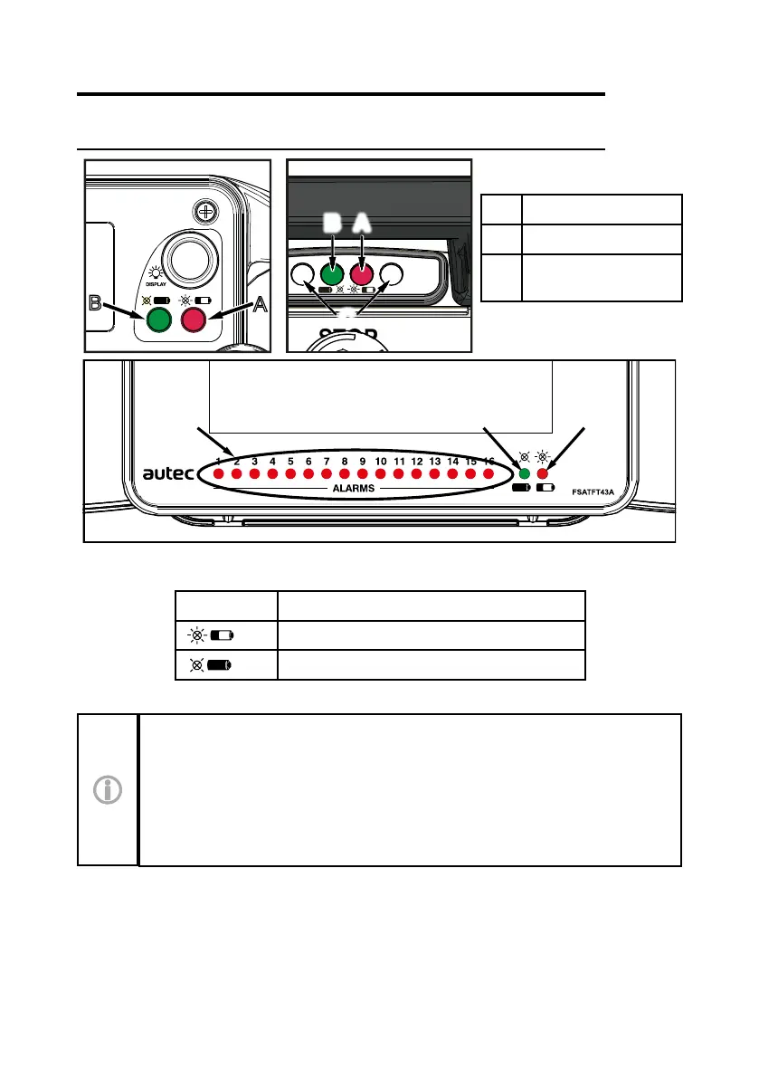
A Red LED
B Green LED
C
LEDs for "Data
Feedback" function
B
C A
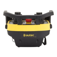
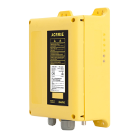
The DJR Transmitting Unit always has a green LED [B] and a red LED [A] that provide
information regarding the Radio Remote Control.
Symbol Meaning
This symbol identies the red LED [A].
This symbol identies the green LED [B].
The meaning of signals provided by the LEDs identied with “C” are explained in
the "Data Feedback" function part (see paragraph 8.14). The meaning of LEDs
related to the "Data Feedback" function are decided and established by the
Machine Manufacturer depending on the Machine's functions for which he wants
to receive information.
Signals provided by the red LED [A] indicate a Radio Remote Control malfunction. The
meaning of these signals and the possible actions to perform are described in chapter 11.