Do you have a question about the AUTEC A08 and is the answer not in the manual?
All manual instructions and warnings must be read and understood before use.
Manufacturer/designer ensures safe integration; user/owner responsible for safe operation.
Compliance with all local laws, safety rules, and standards is mandatory.
Ensure machine structure and markings allow safe remote control use.
Only qualified and trained personnel may operate or be near the machine.
Autec not liable for improper installation, use, or modifications.
Owner/operator must ensure proper maintenance per instructions and laws.
All users must be educated and trained in safe operation and manual instructions.
Areas where the machine operates must be clearly marked to warn personnel.
Failure to comply with safety rules can lead to serious injury, death, or property damage.
Describes the structure of the instruction manual and its different parts (A, B, C, D, E).
Supplemented by Technical Data Sheet for unit configuration and command relations.
CD includes translations; select parts based on serial number and language.
Defines terms like Unit, Radio Remote Control, Transmitting Unit, etc., as used in the manual.
Explains symbols indicating important information and safety warnings.
Refers to the general part for a list of who the instructions are addressed to.
Details on instruction storage and restrictions related to intellectual property.
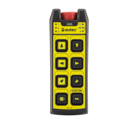
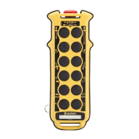
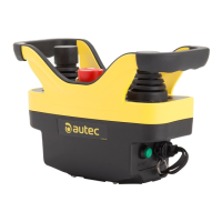
Describes the A8+ Transmitting Unit for Air series Radio Remote Controls.
Information on conformity with standards and contact details for Autec.
Details on warranty conditions and how to obtain technical assistance or spare parts.
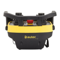
Diagram showing labeled components of the A8+ Transmitting Unit.
Table listing and describing components such as LEDs, pushbuttons, battery, etc.
Lists specifications like power supply, dimensions, weight, run time, and environmental ratings.
Explains the purpose and usage of the Technical Data Sheet, including wiring.
Describes identification and technical data plates on the A8+ Transmitting Unit in a standard Radio Remote Control.
Details plates for 'Take & Release' and 'Multi Units'/'Multi Receiver' configurations.
Identifies the Red LED (A) and Green LED (B) and their general role.
Explains LEDs (C) for 'Data Feedback' function and their manufacturer-defined meanings.
Details the meaning of green LED states: off, steady, blinking sequences, and fast blinking.
Details the meaning of red LED states: off, steady, blinking patterns during startup.
Describes meanings of combined green/red LED patterns during startup and operation.
Explains the function of the power keyswitch for unit activation.
Describes the START pushbutton's function to start the remote and activate the horn.
Details the STOP pushbutton's function to halt the machine and switch off the unit, including safety warnings.
Explains the FUNCTION pushbutton, whose use is defined by the installer.
Details battery requirements and the procedure for inserting the battery.
Procedure for removing the battery from the transmitting unit.
Describes how to check the battery's charge level using the LEDs.
Explains the 'ID internal tx memory' as a key for address coding between units.
Establishes a radio link and is protected by a power keyswitch and optional PIN code.
Procedure for starting the remote control using only the power keyswitch.
Procedure for starting the remote control with both power keyswitch and PIN code.
Steps to modify or set a PIN code for the transmitting unit.
Describes how commands are activated and what happens during radio link interruption.
Explains conditions under which the transmitting unit automatically switches off.
Details how low battery is indicated by LEDs and the consequences.
Explains automatic switch-off due to inactivity and how to reset the timer.
Describes voluntary methods to switch off the transmitting unit and associated safety warnings.
Explains how the 'Data Feedback' function uses LEDs to signal machine conditions.
Notes on interpreting signals and their non-safety critical nature.
Information on using a 'BACK-UP UNIT' for replacement, including DIP switch settings.
Detailed steps for storing the address and PIN code in a backup unit.
Clarifies that user instructions in this part add to general part and do not cover all application specifics.
Details restrictions related to electronic devices, magnetic fields, and battery conversion.
Users must follow all instructions from manufacturer, installer, and manual.
Emphasizes safe operation, avoiding unattended use, and proper handling of the unit.
Users must not modify the unit, its components, or markings.
Instructions on how to insert the transmitting unit into the provided pouch with belt.
User must wear the remote with the pouch to prevent falls, loss, or accidents.
Using the unit with the pouch differently from described is improper use and may cause damage.
Replace the pouch with belt if it is damaged or worn.
Refers to Part A of the manual for correct maintenance instructions.
Lists malfunctions signaled by LEDs on the transmitting unit and their solutions.
Details further LED signals for malfunctions like incorrect memory or START activation.
Refers to Part A of the manual for correct decommissioning and disposal procedures.
| Operating Temperature | -20°C to +55°C |
|---|---|
| Enclosure Protection | IP65 |
| IP Rating | IP65 |
| Operating Voltage | 3.0 V DC |
| Operating Range | 100 meters |
| Frequency Band | 433.050 - 434.790 MHz, 915 - 928 MHz |
| Frequency | 433.1 - 434.79 MHz or 915 - 928 MHz |