OM-157 066 Page 10
2-11. Electrical Service Guide
Input Voltage 200 230 460 575
Input Amperes At Rated Output 46 40 20 16
Max Recommended Standard Fuse Or Circuit Breaker Rating In Amperes
Circuit Breaker
1
, Time-Delay Fuse
2
50 50 25 20
Normal Operating Fuse
3
70 60 30 25
Min Input Conductor Size In AWG/Kcmil 10 10 14 14
Max Recommended Input Conductor Length In Feet (Meters)
59
(18)
77
(24)
122
(37)
190
(58)
Min Grounding Conductor Size In AWG/Kcmil 10 10 14 14
Reference: 1999 National Electrical Code (NEC)
1 Choose a circuit breaker with time-current curves comparable to a Time Delay Fuse.
2 “Time-Delay” fuses are UL class “RK5” .
3 “Normal Operating” (general purpose – no intentional delay) fuses are UL class “K5” (up to and including 60 amp), and UL class “H” ( 65 amp and
above).
Y Caution: Failure to follow these fuse and circuit breaker recommendations could create an electric shock or fire hazard.
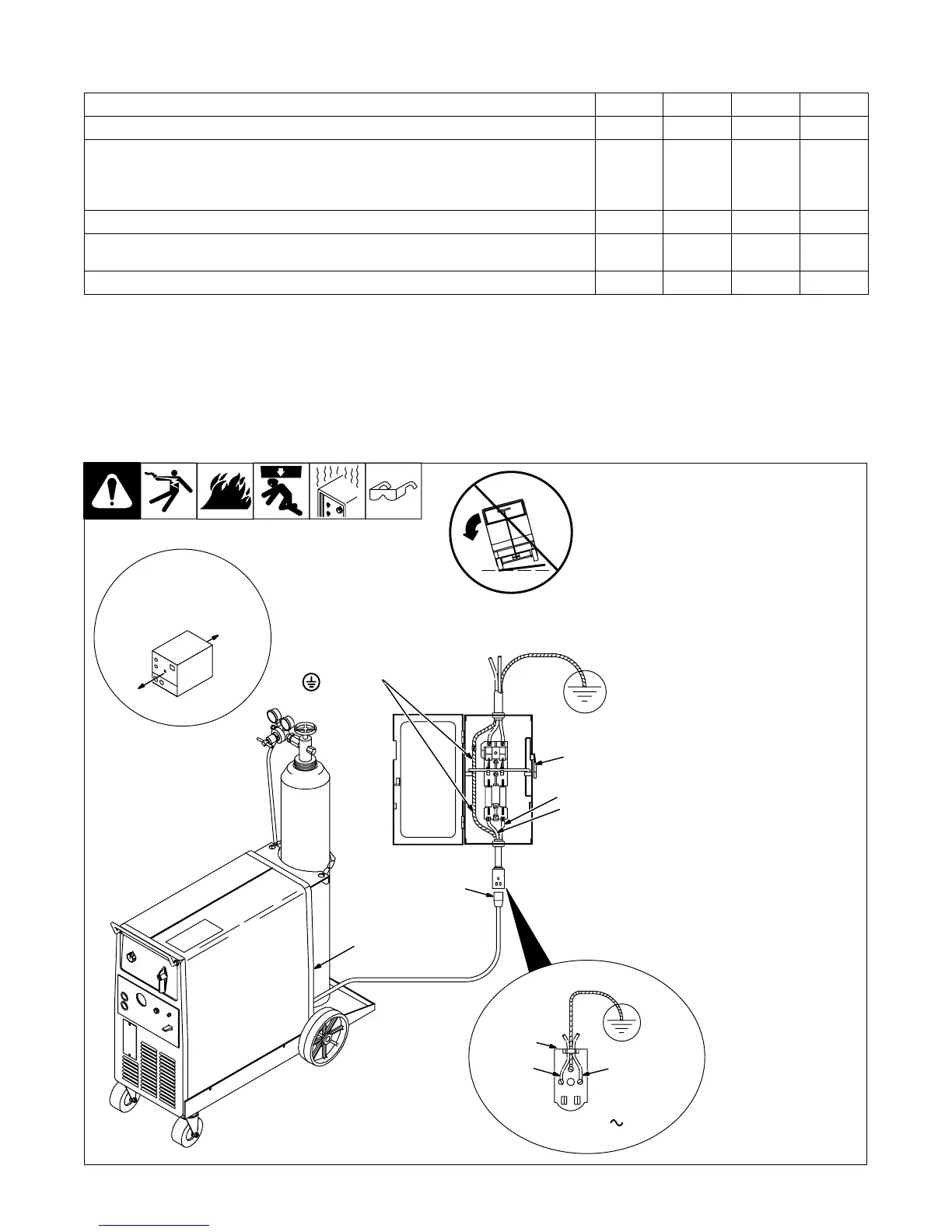
2-12. Selecting A Location And Connecting Input Power
1 Rating Label
Supply correct input power.
2 Plug
3 Receptacle
Connect plug to receptacle.
4 Line Disconnect Device
See Section 2-11.
Y Special installation may be
required where gasoline or
volatile liquids are present –
see NEC Article 511 or CEC
Section 20.
ST-800 923-A
L1L2
230 VAC, 1
18 in (457 mm) of
space for airflow
L1
L2
1
Y Do not move or operate unit
where it could tip.
Y Always connect
grounding conductor first.
= GND/PE
3
2
4