SYSTEM DESCRIPTION
AutoGyro_FOM_MTOsport Revision 5.0 – Issue Date 01.04.2011 7-5
7.8 Rotor System
The two-bladed, semi-rigid, teetering rotor system comprises high-strength aluminium
extruded rotor blades, a hub bar, and a common teeter hinge assembly.
The rotor blades feature an aerodynamic profile especially suitable for rotorcraft which, in
combination with its relative centre of gravity, provides aerodynamic stability by eliminating
negative blade pitching moments and flutter tendency. The hollow blade profile is sealed at
both ends by plastic blade caps.
The aluminium rotor hub bar is pre-coned to the natural coning angle of the blades and
connects the blades firmly to each side using 6 fitting bolts (9 bolts in earlier hub bars) and
a clamping profile. In order to compensate for asymmetric air flow in forward flight the
blades are free to teeter. The hinge assembly consists of teeter tower, teeter bolt and teeter
block.
The teeter bolt runs in a long Teflon coated bushing in the teeter block (main bearing
action), as well as two shorter bushings in the teeter tower (emergency bearing action). The
main bearing action is supported by special grease which is applied through a grease nipple
on top of the teeter block. Servicing is described in SECTION 8 of this manual.
7.9 Flight Controls
Rotor head and trim control
Pitch and roll of the gyroplane are controlled by tilting the complete rotor head by means of
the control stick. Control input is transferred via torsion tube and linkage running below the
seats to the base link and from there to the rotor head via two split control rods with ball
ends.
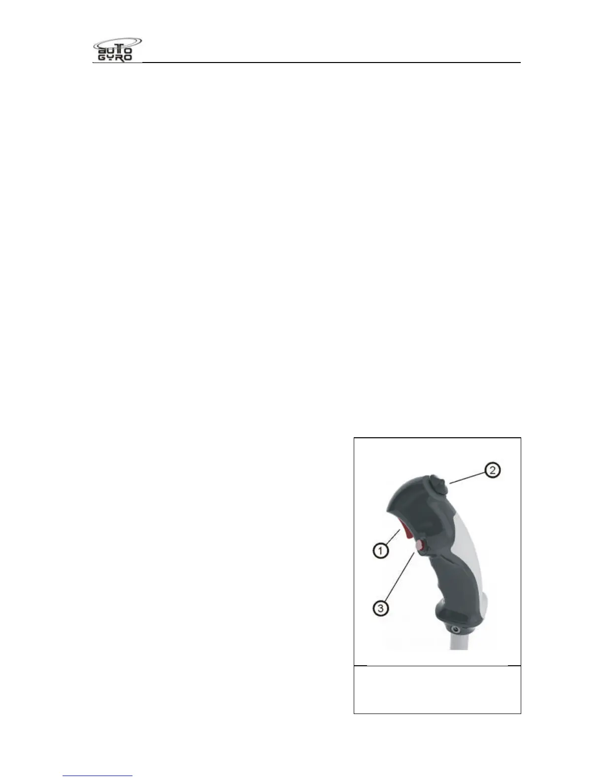
The control stick head is ergonomically shaped to
fit the pilot’s right hand and features control buttons
for radio transmission (1), a four-way trim function
(2), and activation of the pre-rotator (3).
The trim control works as a classical 4-way beep
switch. Pulling the beep switch back increases aft
trim or nose-up tendency, while pushing the switch
forward reduces back trim pressure, leading to a
nose-down tendency. Lateral trim input is not
active on MTOsport models.
Because of a safety circuit, activation of the pre-
rotator is only possible with the pneumatic mode
selector in FLIGHT position and the control stick
fully forward. This prevents inadvertent activation
of the pre-rotator during flight or in BRAKE mode.
The aft stick is held by means of 2 bolts, self-
locking nuts and a pair of distance washers within
a bracket and must be removed unless the seat is
occupied by a qualified flight instructor.
 Loading...