HANDLING / MAINTENANCE
AutoGyro_FOM_MTOsport Revision 5.0 – Issue Date 01.04.2011 8-7
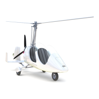
3. Push out all fitting bolts (4) without any force, but use no more than a gentle tapping if
necessary. Tilt the rotor blade up and down to support easy removal of the bolt.
4. Carefully pull the rotor blade out of the hub (1) in radial direction and take off the
clamping profile (2).
5. Repeat step 2 to 4 on second rotor blade.
6. Do not disassemble the rotor hub!
7. Store and transport rotor blades, clamping profile and rotor hub only in air cushion foil
or using other suitable means to prevent bending or surface damage.
1 – Rotor hub 4 – Fitting bolts (6 ea.)
2 – Clamping profile 5 – Washer (12 ea.)
3 – Rotor blade 6 – Lock nuts (6 ea.)
8.15.3 Assembly of the Rotor System
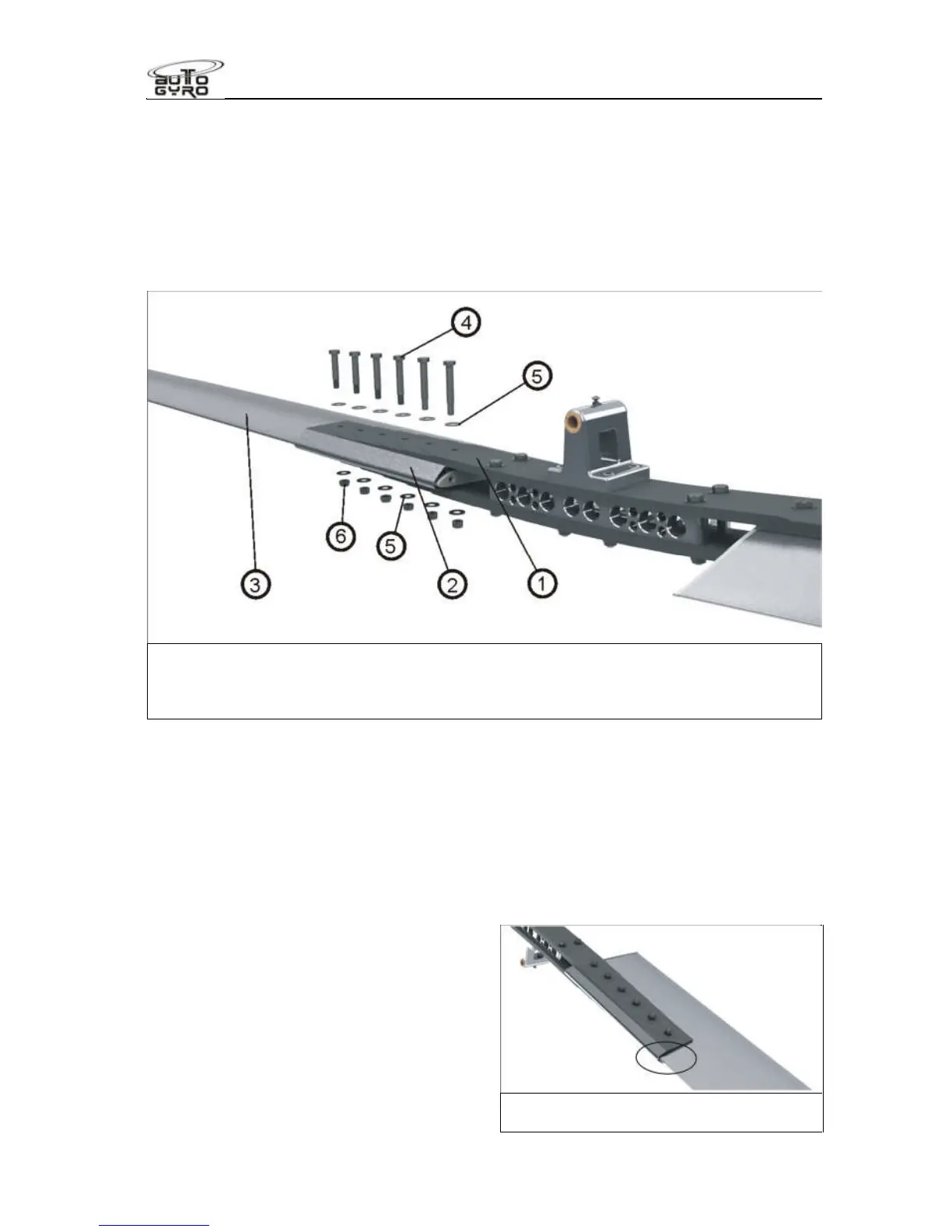
1. The rotor blades, clamping profile and rotor hub are labelled with an engraved serial
number.
2. Insert the first rotor blade carefully into the clamping profile. Make sure that all serial
numbers match.
3. Fit the rotor hub side with the according serial number to clamping profile and blade.
Insert fitting bolts without using force so that the bolt end is on top when the rotor
system is installed.
4. Position the washers and the locknut
and hand-tighten all nuts.
5. Torque-tighten nuts with 15 Nm from
the inside to the outside, using a torque
wrench. When doing so, counter-hold
bolts to prevent any damage the hub
and blade holes.
6. Repeat steps 2 to 5 for the second
rotor blade.
Position where serial numbers are
engraved (bottom side)
 Loading...