K50 LOGIC CONTROL BOARD INSTALLATION
BOARD INTERFACE
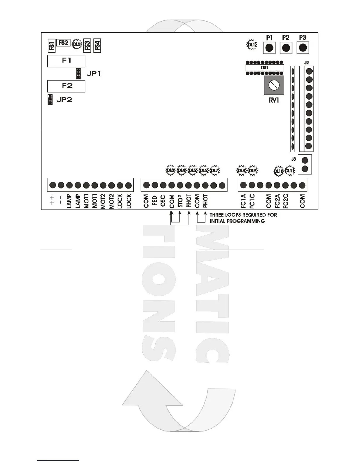
COMPONENTS TERMINALS – LEFT TO RIGHT
FS1-2 Battery charge plug 12-24 Vdc 12Vdc/24Vac Choose via jumper JP2 Pos 1&2 = 12V
FS3-4 Power supply input 12-20 Vac LAMP Flashing light output
F1 Battery Fuse 10A Fast MOT1 Output for motor 1 10A Max
F2 Output Fuse 2A Slow MOT2 Output for motor 2 10A Max
JP1 Battery Charge Selector 12/24Vdc LOCK Output for electric lock 12Vdc 1A
JP2 Output Selector 12/24Vdc COM Common for open inputs PED & OSC
DL1 Programming LED PED Pedestrian open input (NO)
DL2 Power Supply LED START Open/Stop/Close input (NO)
DL3 DL4 Open Input LED COM Common for STOP & PHOTO inputs
DL5 DL6 DL7 Stop & Photo LED STOP Stop input (NC)
DL8 DL9 Motor1 Limit Switch LED PHOTO Photocell Input (NC)
DL10 DL11 Motor2 Limit Switch LED COM Photocell 2 common
J3 Antenna Connector PHOTO Photocell 2 Input (NC)
J2 External receiver connector FC1A Limit switch 1 opening input (NC)
RV1 Slowing speed regulator FC1C Limit switch 1 closing input (NC)
DS1 Setting Up Dip Switches COM Common for limit switch 1
P1 Radio code programming button FC2A Limit switch 2 opening input (NC)
P2 Working time programming button FC2C Limit switch 2 closing input (NC)
P3 Pause time programming button COM Common for limit switch 2