Terminal board J5
Terminal1 – Aerial cable connection (shield) for radio receiver card
Terminal2 – Aerial cable connection (signal) for radio receiver card
Terminal board J1
Terminal1 - Power supply positive for photo-cells or other devices
Terminal2 - Power supply negative for photo-cells or other devices (common)
Terminal3 - Power supply positive for blinker
Terminal4 - Power supply negative for blinker (common)
Terminal5 - Motor M1 power supply
Terminal6 - Motor M1 power supply
Terminal7 - Motor M2 power supply
Terminal8 - Motor M2 power supply
Terminal9 – Power supply positive for electric lock
Terminal10 – Power supply negative for electric lock (common)
Terminal board J3
Terminal1 - Motor 1 opening Limit switch normally closed electric contact
Terminal2 - Motor 1 closing Limit switch normally closed electric contact
Terminal3 - Motor 1 Encoder signal input
Terminal4 - Common terminal for Motor 1 Limit switches and Encoder
Terminal5 - Motor 2 opening Limit switch normally closed electric contact
Terminal6 - Motor 2 closing Limit switch normally closed electric contact
Terminal7 - Motor 2 Encoder signal input
Terminal8 - Common terminal for Motor 2 Limit switches and Encoder
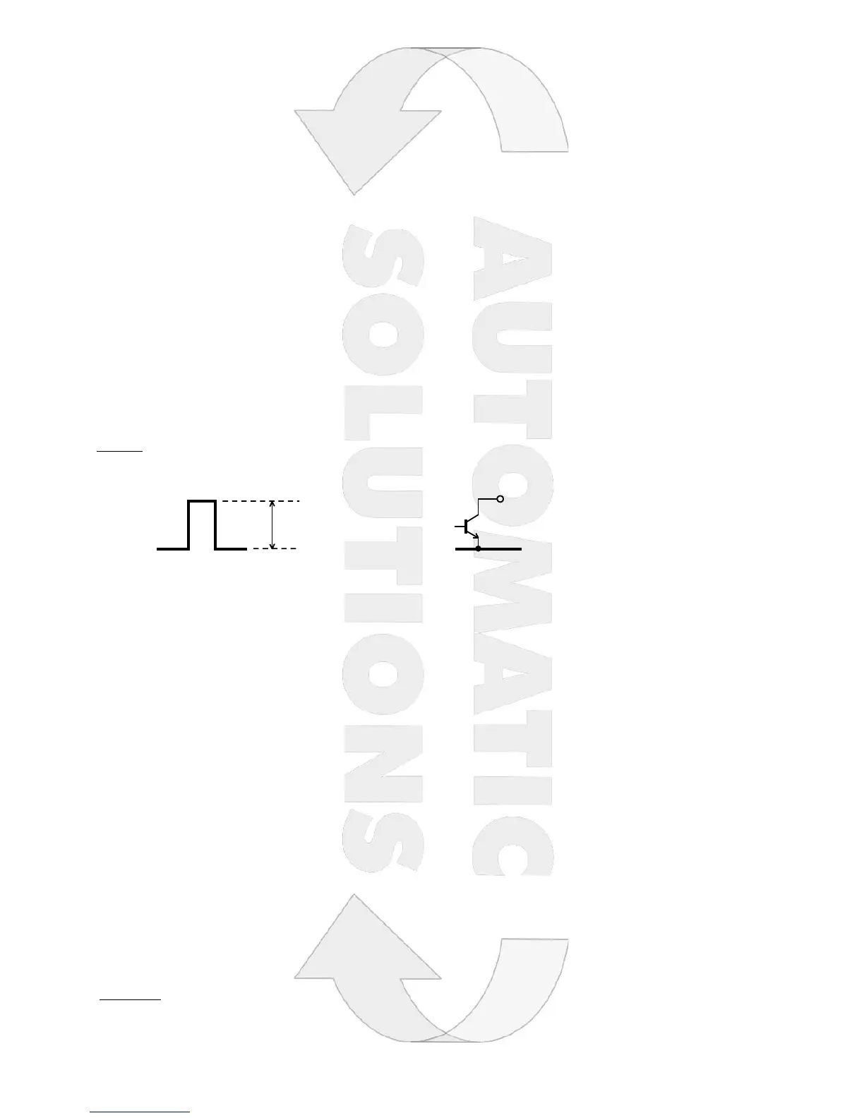
Important: The equipment only accepts a “TTL” or “OPEN COLLECTOR” input as Encoder signal.
TTL OPEN COLLECTOR
FS1 Faston – Backup battery’s positive pole connection
FS2 Faston – Backup battery’s negative pole connection
FS3 Faston – 12/15/20 Vac power supply from the electric transformer
FS4 Faston – 12/15/20 Vac power supply from the electric transformer
CTR50 - Connection of the devices
Motor 1 – Terminals 5 and 6 on J1
Motor 2 – Terminals 7 and 8 on J1
Blinker – Terminals 3 and 4 on J1
Electric lock – Terminals 9 and 10 on J1
Photo-cells power supply – Terminals 1 and 2 on J1
NC photo-cell contact – Terminals 4 and 6 on J2
NC stop push-button – Terminals 4 and 5 on J2
NC photostop contact – Terminals 7 and 8 on J2
NO start push-button – Terminals 1 and 3 on J2
NO pedestrian start push-button – Terminals 1 and 2 on J2
Aerial – Terminals 1 and 2 on J5
Open gate lamp - Terminals 9 e 10 on J1
NC Motor 1 opening limit switch contact – Terminals 1 and 4 on J3
NC Motor 1 closing limit switch contact – Terminals 2 and 4 on J3
NC Motor 2 opening limit switch contact – Terminals 5 and 8 on J3
NC Motor 2 closing limit switch contact – Terminals 6 and 8 on J3
Motor 1 Encoder connection - Terminals 3 and 4 on J3
Motor 2 Encoder connections - Terminals 7 and 8 on J3
IMPORTANT:
If no cable is connected to the FC1A and FC1C inputs, the control of Motor 1 limit switches will be automatically disabled.
If no cable is connected to the FC2A and FC2C inputs, the control of Motor 2 limit switches will be automatically disabled.
 Loading...