4– TESTS
4.1 Precautions
Before carrying out the tests, make sure:
That the transformer is not powered.
To carefully check the wiring system.
That the electric interlocking system is powered so that the loops can be tested
up to the final element (e.g. LED for alarm function, actuators
for trigger function).
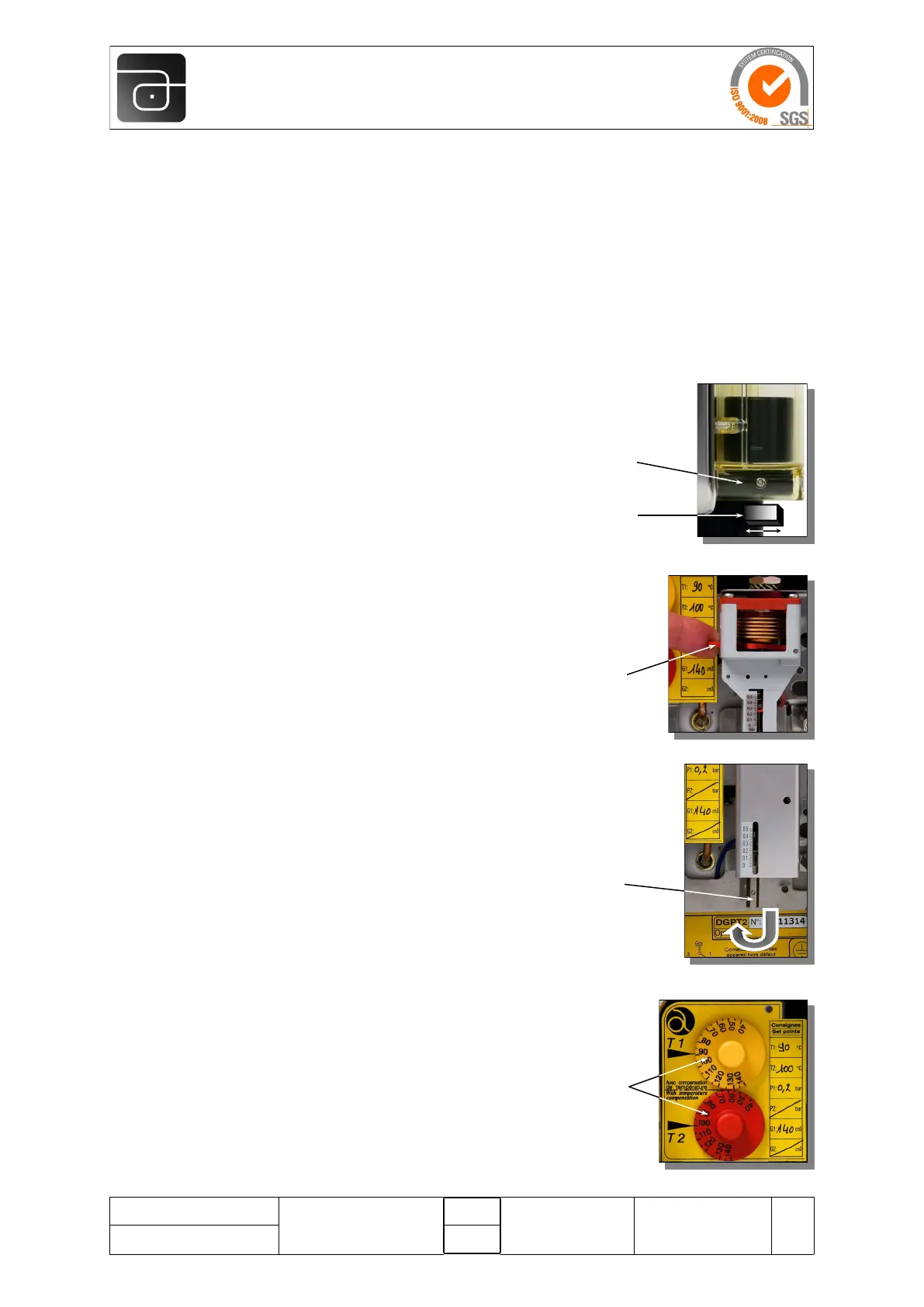
4.2 Gas discharge
Element concerned: Reed contact
Moving a magnet (minimum Ø 22 mm, thickness
10 mm) under the Reed housing (or on the side) will
change the contact’s position.
Check that the loop is operating correctly.
4.3 Excessive pressure
Element concerned: Pressure switch type 1
Press the test button located on the left side of the
pressure switch.
The contact changes position.
Check that the loop is operating correctly,
then release the test button.
Element concerned: Pressure switch type 2
Turn the setting knob clockwise to bring the
set-point to zero.
The contact changes position.
Check that the loop is operating correctly, then reset
the set-point at the value indicated on the yellow
identification plate.
4.4 Temperature
Elements concerned: T1 and T2 thermostats
Turn the setting knob below its 40°C graduation.
The contact changes position.
Check that the loop is operating correctly, then reset
the set-point at the value indicated on the yellow
identification plate.
Test
button
Reed
housing
Magnet
Setting
knob
Setting
knobs
TYPE 2
TYPE 1
AUTOMATI ON 20 0 0
TECH. INSTRUCTIONS
Page
N° T/NOT-0021 Date: 28/09/16
Rev.
7
DGPT2
®
7