DL06 Micro PLC User Manual, 3rd Edition, Rev. E
3-16
Chapter 3: CPU Specifications and Operation
1
2
3
4
5
6
7
8
9
10
11
12
13
14
A
B
C
D
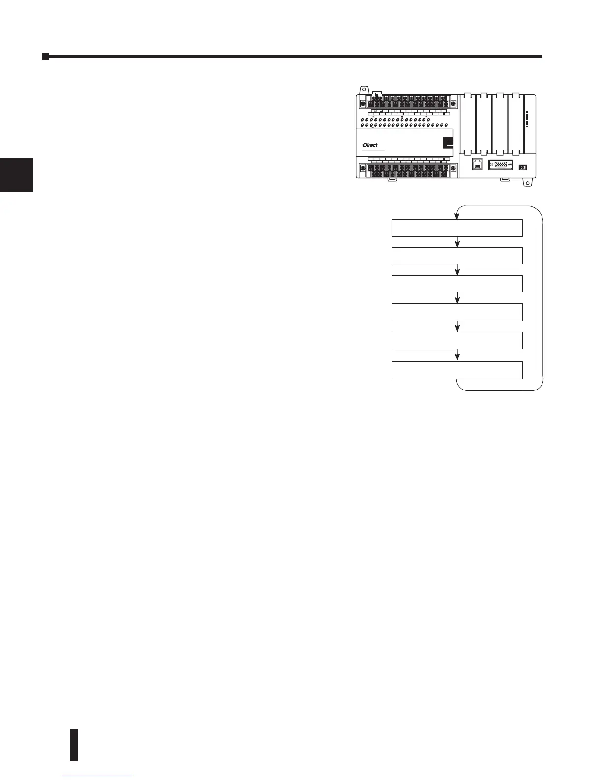
Solve Application Program
The CPU evaluates each instruction in the
application program during this segment of the
scan cycle. The instructions define the relationship
between the input conditions and the desired
output response. The CPU uses the output image
register area to store the status of the desired action
for the outputs. Output image register locations
are designated with a Y followed by a memory
location. The actual outputs are updated during the
write outputs segment of the scan cycle. There are
immediate output instructions available that will
update the output points immediately instead of
waiting until the write output segment. A complete
list of the Immediate instructions is provided in
Chapter 5.
The internal control relays (C), the stages (S), and
the variable memory (V) are also updated in this
segment.
You may recall that you can force various types
of points in the system, discussed earlier in this
chapter. If any I/O points or memory data have been
forced, the output image register also contains this
information.
Solve PID Loop Equations
The DL06 CPU can process up to 8 PID loops. The loop calculations are run as a separate
task from the ladder program execution, immediately following it. Only loops which have been
configured are calculated, and then only according to a built-in loop scheduler. The sample
time (calculation interval) of each loop is programmable. Please refer to Chapter 8, PID Loop
Operation, for more on the effects of PID loop calculation on the overall CPU scan time.
Write Outputs
Once the application program has solved the instruction logic and constructed the output
image register, the CPU writes the contents of the output image register to the corresponding
output points. Remember, the CPU also made sure that any forcing operation changes were
stored in the output image register, so the forced points get updated with the status specified
earlier.
Write Outputs to Specialty I/O
After the CPU updates the outputs in the local and expansion bases, it sends the output point
information that is required by any Specialty modules which are installed. Specialty modules
have built-in microprocessors which communicate to the CPU via the backplane. Some of
these modules can process data. Refer to the specific Specialty module user manual for detailed
information.
 Loading...


