DL06 Micro PLC User Manual, 3rd Edition, Rev. E
3-29
Chapter 3: CPU Specifications and Operation
1
2
3
4
5
6
7
8
9
10
11
12
13
14
A
B
C
D
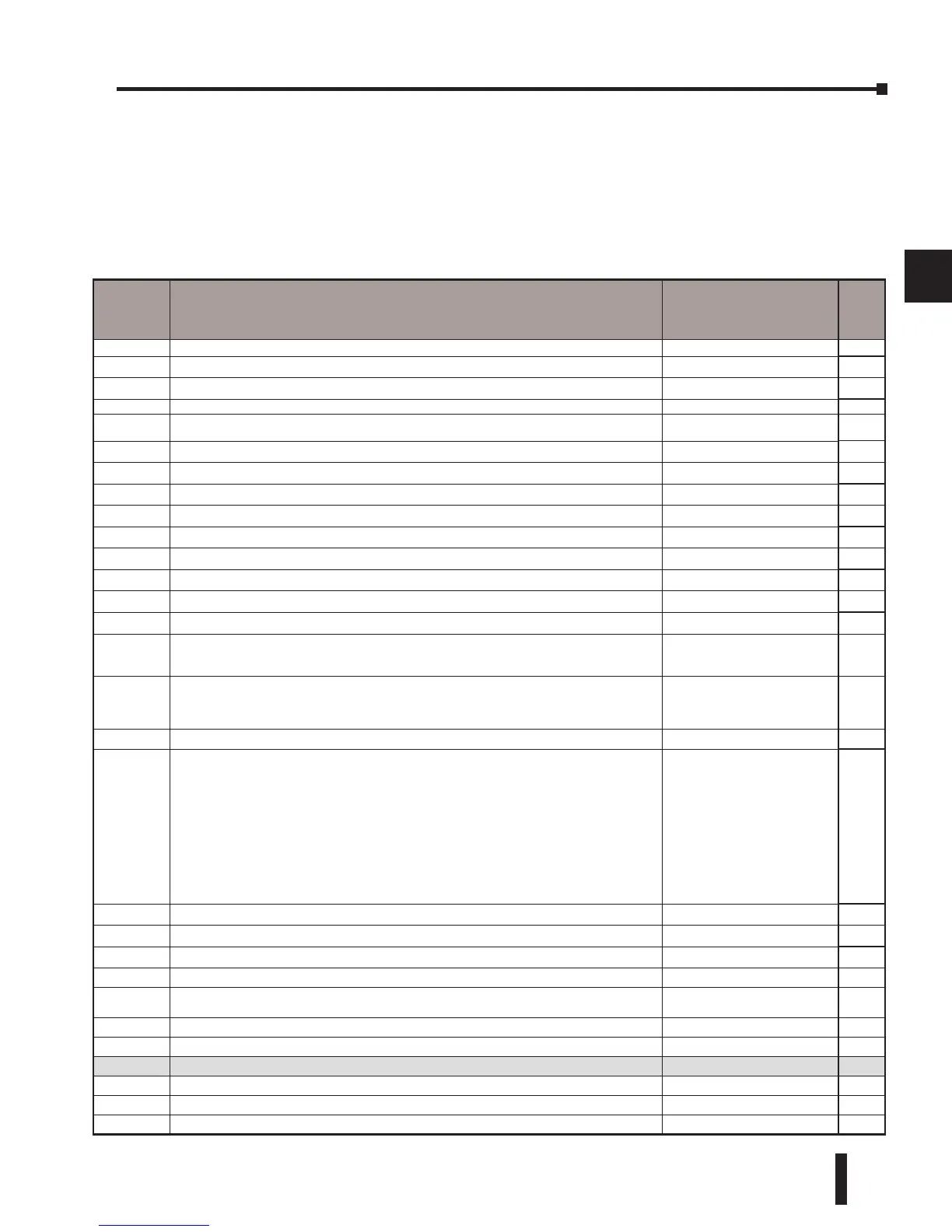
DL06 System V-memory
System Parameters and Default Data Locations (V Data Type)
The DL06 PLCs reserve several V-memory locations for storing system parameters or certain
types of system data. These memory locations store things like the error codes, High-Speed I/O
data, and other types of system setup information.
System
V-memory
Description of Contents Default Values / Ranges
Read
Only
R/W
V700-V707 Sets the V-memory location for option card in slot 1 N/A R/W
V710-V717 Sets the V-memory location for option card in slot 2 N/A R/W
V720-V727 Sets the V-memory location for option card in slot 3 N/A R/W
V730-V737 Sets the V-memory location for option card in slot 4 N/A R/W
V3630–V3707 The default location for multiple preset values for UP/DWN and UP Counter 1 or pulse catch function N/A R/W
V3710-V3767 The default location for multiple preset values for UP/DWN and UP Counter 2 N/A R/W
V7620 DV-1000 Sets the V-memory location that contains the value V0 – V3760 R/W
V7621 DV-1000 Sets the V-memory location that contains the message V0 – V3760 R/W
V7622 DV-1000 Sets the total number (1 – 32) of V-memory locations to be displayed 1 - 32 R/W
V7623 DV-1000 Sets the V-memory location containing the numbers to be displayed V0 – V3760 R/W
V7624 DV-1000 Sets the V-memory location that contains the character code to be displayed V0 – V3760 R/W
V7625 DV-1000 Contains the function number that can be assigned to each key V-memory for X, Y, or C R/W
V7626 DV-1000 Powerup operational mode 0,1, 2, 3, 12 R/W
V7627 Change preset value 0000 to 9999 R/W
V7630
Starting location for the multi–step presets for channel 1. The default value is 3630, which indicates
the first value should be obtained from V3630. Since there are 24 presets available, the default range
is V3630 – V3707. You can change the starting point if necessary.
Default: V3630
Range: V0- V3710
R/W
V7631
Starting location for the multi–step presets for channel 2. The default value is 3710, which indicates
the first value should be obtained from V3710. Since there are 24 presets available, the default range
is V3710 – V3767. You can change the starting point if necessary.
Default: V3710
Range: V0- V3710
R/W
V7632 Setup Register for Pulse Output N/A R/W
V7633
Sets the desired function code for the high speed counter, interrupt, pulse catch, pulse train, and
input filter.
This location can also be used to set the power-up in Run Mode option.
Default: 0060
Lower Byte Range: Range: 10
– Counter 20 – Quadrature 30 –
Pulse Out 40 – Interrupt 50 – Pulse
Catch 60 – Filtered discrete In.
Upper Byte Range: Bits 8–11, 14,
15: Unused, Bit 13: Power–up in
RUN, only if Mode Switch is in
TERM position. Bit 12 is used to
enable the low battery indications.
R/W
V7634 X0 Setup Register for High-Speed I/O functions for input X0 Default: 1006 R/W
V7635 X1 Setup Register for High-Speed I/O functions for input X1 Default: 1006 R/W
V7636 X2 Setup Register for High-Speed I/O functions for input X2 Default: 1006 R/W
V7637 X3 Setup Register for High-Speed I/O functions for input X3 Default: 1006 R/W
V7640 PID Loop table beginning address
V1200 - V7377
V10000-V17777
R/W
V7641 Number of PID loops enabled 1-8 R/W
V7642 Error Code - PID Loop Table R
V7643-V7646 DirectSoft I-Box instructions work area R
V7647 Timed Interrupt R/W
V7653 Port 2: Terminate code setting Non-procedure R/W
V7655 Port 2: Setup for the protocol, time-out, and the response delay time R/W
 Loading...


