DL06 Micro PLC User Manual; 3rd Edition Rev. E
4–24
Chapter 4: System Design and Configuration
1
2
3
4
5
6
7
8
9
10
11
12
13
14
A
B
C
D
MRX Slave Memory Address
MRX Master Memory Addresses
MRX Number of Elements
MRX Exception Response Buffer
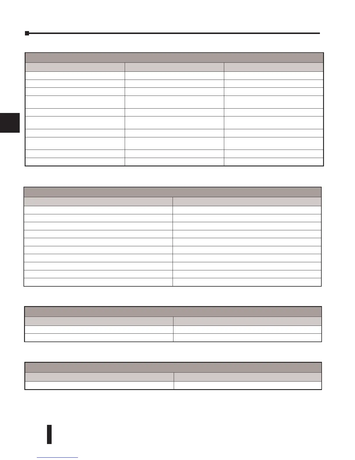
MRX Slave Address Ranges
Function Code MODBUS Data Format Slave Address Range(s)
01 – Read Coil 484 Mode 1–999
01 – Read Coil 584/984 Mode 1–65535
02 – Read Input Status 484 Mode 1001–1999
02 – Read Input Status 584/984 Mode
10001–19999 (5 digit) or 100001–165535
(6 digit)
03 – Read Holding Register 484 Mode 4001–4999
03 – Read Holding Register 584/984
40001–49999 (5 digit) or 4000001–465535
(6 digit)
04 – Read Input Register 484 Mode 3001–3999
04 – Read Input Register 584/984 Mode
30001–39999 (5 digit) or 3000001–365535
(6 digit)
07 – Read Exception Status 484 and 584/984 Mode n/a
08 – Diagnostics 484 and 584/984 Mode 0–65535
MRX Master Memory Address Ranges
Operand Data Type DL06 Range
Inputs X 0–1777
Outputs Y 0–1777
Control Relays C 0–3777
Stage Bits S 0–1777
Timer Bits T 0–377
Counter Bits CT 0–377
Special Relays SP 0–777
V–memory V All
Global Inputs GX 0–3777
Global Outputs GY 0–3777
MRX Number of Elements
Operand Data Type
DL06 Range
V–memory V All
Constant K 1–2000
MRX Exception Response Buffer
Operand Data Type DL06 Range
V–memory V All