DL06 Micro PLC User Manual, 3rd Edition, Rev. E
5-126
Chapter 5: Standard RLL Instructions
1
2
3
4
5
6
7
8
9
10
11
12
13
14
A
B
C
D
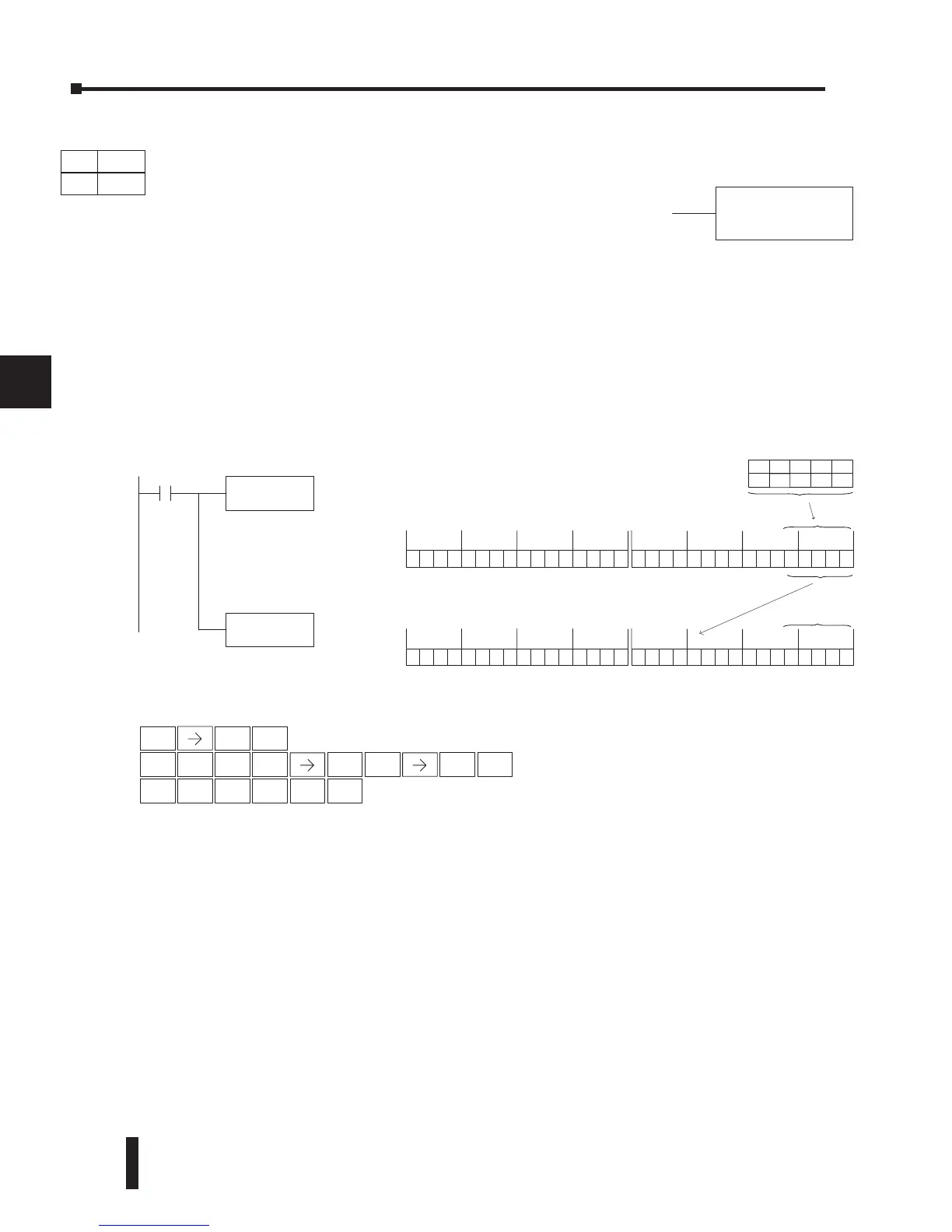
In the following example when X1 is on, the value formed by discrete locations X10–X14 is
loaded into the accumulator using the Load Formatted instruction. The 5- bit binary pattern in
the accumulator is decoded by setting the corresponding bit position to a “1” using the Decode
instruction.
Handheld Programmer Keystrokes
Direct SOFT32
LDF X10
K5
X1
Load the value in
represented by discrete
locations X10–X14 into the
accumulator
DECO
Decode the five bit binary
pattern in the accumulator
and set the corresponding
bit position to a “1”
X10 X11 X13 X12
ON ON OFF
X14
OFF ON
00000000000010 110000000000000000
15 14 13 12 11 10 9 876543210
31 30 29 28 27 26 25 24 23 22 21 20 19 18 17 1631 30 29 28 27 26 25 24 23 22 21 20 19 18 17
16
Acc.
00001000000000 000000000000000000
15 14 13 12 11 10 9 876543210
31 30 29 28 27 26 25 24 23 22 21 20 19 18 17 1631 30 29 28 27 26 25 24 23 22 21 20 19 18 17
16
Acc.
The binary vlaue
is converted to
bit position 11.
STR
$
ENT
SHFT
ANDST
L
3
D
5
F
1
B
1
B
0
A
ENT
5
F
SHFT
2
C
INST#
O
ENT
3
D
4
E
DECO
DS Used
HPP Used
DirectSOFT
Decode (DECO)
The Decode instruction decodes a 5-bit binary value of 0–31
(0–1Fh) in the accumulator by setting the appropriate bit
position to a 1. If the accumulator contains the value Fh (HEX),
bit 15 will be set in the accumulator. If the value to be decoded
is greater than 31, the number is divided by 32 until the value is
less than 32 and then the value is decoded.


 To Next Page