DL06 Micro PLC User Manual, 3rd Edition, Rev. E
5-184
Chapter 5: Standard RLL Instructions
1
2
3
4
5
6
7
8
9
10
11
12
13
14
A
B
C
D
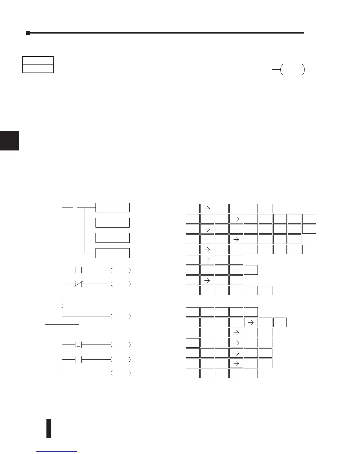
External Interrupt Program Example
In the following example, we do some initialization on the first scan, using the first-scan contact
SP0. The interrupt feature is the HSIO Mode 40. Then, we configure X0 as the external
interrupt by writing to its configuration register, V7634. See Appendix E, Mode 40 Operation
for more details.
During program execution, when X2 is on, the interrupt is enabled. When X2 is off, the
interrupt will be disabled. When an interrupt signal (X0) occurs, the CPU will jump to the
interrupt label INT O 0. The application ladder logic in the interrupt routine will be performed.
The CPU will return to the main body of the program after the IRT instruction is executed.
DISI
DirectSOFT
O 0
X2
ENI
DISI
X2
END
Y5
SETI
X1
Y7
SETI
X3
IRT
Handheld Programmer Keystrokes
8
I
ORN
R
MLR
T
STR
$
SHFT
8
I
1
B
ENT
SHFT
8
I
5
F
ENT
STR
$
SHFT
8
I
3
D
ENT
SHFT
8
I
ENT
7
H
SHFT
4
E
TMR
N
3
D
ENT
STR
$
ENT
2
C
SHFT
4
E
TMR
N
8
I
ENT
STRN
SP
ENT
2
C
SHFT
8
I
TMR
N
MLR
T
0
A
ENT
SHFT
ENT
SHFT
ENT
3
D
8
I
RST
S
8
I
SET
X
SET
X
LD
K40
SP0
Load the constant value
(K40) into the lower 16 bits
of the accumulator
OUT
V7633
Copy the value in the lower
16 bits of the accumulator to
V7633
LD
K4
Load the constant value (K4)
into the lower 16 bits of the
accumulator
OUT
V7634
Copy the value in the lower
16 bits of the accumulator to
V7634
STR
$
SHFT
ANDST
L
3
D
SHFT
OUT
GX
SHFT
AND
V
ENT
JMP
K
ENT
7
H
6
G
3
D
4
E
SHFT
ANDST
L
3
D
SHFT
0
A
OUT
GX
SHFT
AND
V
ENT
JMP
K
4
E
ENT
7
H
6
G
3
D
3
D
4
E
SHFT
ENT
STRN
SP
0
A
INT
DS Used
HPP Used
Disable Interrupts (DISI)
A Disable Interrupt instruction in the main body of the application
program (before the End instruction) will disable the interrupt (either
external or timed). The interrupt remains disabled until the program
executes an Enable Interrupt instruction.


 To Next Page