DL06 Micro PLC User Manual, 3rd Edition, Rev. E
Chapter 2: Installation, Wiring, and Specifications
1
2
3
4
5
6
7
8
9
10
11
12
13
14
A
B
C
D
2-5
WARNING: For some applications, field device power may still be present on the terminal block
even though the Micro PLC is turned off. To minimize the risk of electrical shock, check all field
device power before you expose or remove either connector.
LOGI
C
Koyo
0
6
C0 C4C2X1 X3 X4 X6 X11 X13 X14 X16 X21X23 N.C.
C1 C3X2 X5 X7 X10 X12 X15X17 X20X22X0
N.C.
AC
(
N
)
24V
0V
N.C.
C1 C3Y0 Y15Y12Y10Y17Y7Y5Y2
C0 C2 Y16Y14Y13Y11Y6Y4Y3Y1
LG
G
AC
(
L
)
D0-06DR
2.0AOUTPUT: 6-240V 50 - 60Hz 2.0A, 6 - 27V
INPUT: 12 - 24V3 - 15mA
Y
X
40VA50-60HzPWR: 100-240V
0 12345671011121314151617202122
23
PORT1PORT2
TERM
RUN STOP
PWR
RUN
CPU
TX1
RX1
TX2
RX2
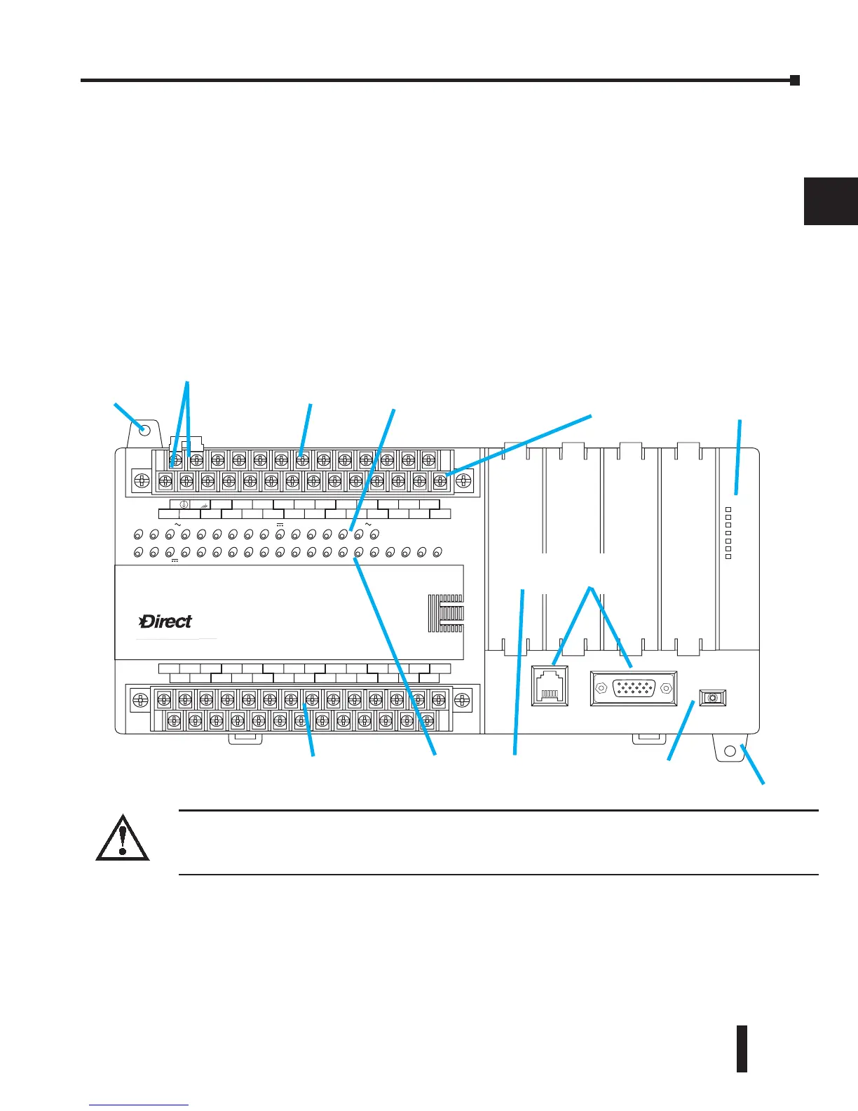
Mode SwitchOption Slots
Output Status
Indicators
Communication
Ports
Output Circuit
Power Input
(for DC output versions only)
Input Status
Indicators
Status
Indicators
Power Inputs
Discrete Outputs
Discrete Inputs
Mounting Tab
Mounting Tab
Orientation to DL06 Front Panel
Most connections, indicators and labels on the DL06 Micro PLCs are located on its front
panel. The communication ports are located on front of the PLC, as are the option card slots
and the mode selector switch. Please refer to the drawing below.
The output and power connector accepts external power and logic and chassis ground
connections on the indicated terminals. The remaining terminals are for connecting commons
and output connections Y0 through Y17. The sixteen output terminals are numbered in
octal, Y0-Y7 and Y10-Y17. On DC output units, the end terminal on the right accepts power
for the output stage. The input side connector provides the location for connecting the inputs
X0 and X23 and the associated commons.