DL06 Micro PLC User Manual, 3rd Edition, Rev. E
Chapter 2: Installation, Wiring, and Specifications
1
2
3
4
5
6
7
8
9
10
11
12
13
14
A
B
C
D
2-11
Wiring Guidelines
Connect the power input wiring for the DL06. Observe all precautions stated earlier in this
manual. When the wiring is complete, close the connector covers. Do not apply power at
this time.
WARNING: Once the power wiring is connected, secure the terminal block cover in the closed
position. There is a risk of electrical shock if you accidentally touch the connection terminals or
power wiring when the cover is open.
External Power Source
The power source must be capable of suppling voltage and current complying with
individual Micro PLC specifications, according to the following specifications:
NOTE: The rating between all internal circuits is BASIC INSULATION ONLY.
NOTE: Recommended wire size for field devices is 16–22 AWG solid/stranded. Tighten terminal
screws to 7.81 lb·in (0.882 N·m) to 9.03 lb-in (1.02 N·m).
+
-
12 - 24 VDC
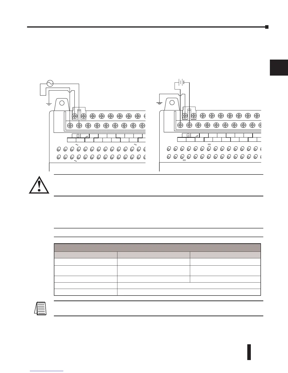
110/220 VAC Power Input
12/24 VDC Power Input
Power Source Specifications
Item DL06 AC Powered Units DL06 DC Powered Units
Input Voltage Range 110/220 VAC (100–240 VAC/50-60 Hz) 12–24 VDC (10.8–26.4 VDC)
Maximum Inrush Current
13A, 1ms (100–240 VAC)
15A, 1ms (240–264 VAC)
10A
Maximum Power 40VA 20W
Voltage Withstand (dielectric) 1 minute @ 1500VAC between primary, secondary, field ground
Insulation Resistance > 10Mq at 500VDC