DL06 Micro PLC User Manual, 3rd Edition, Rev. E
Chapter 2: Installation, Wiring, and Specifications
1
2
3
4
5
6
7
8
9
10
11
12
13
14
A
B
C
D
2-13
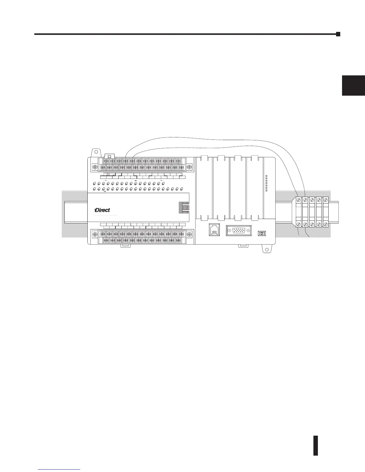
Fuse Protection for Input and Output Circuits
Input and Output circuits on DL06 Micro PLCs do not have internal fuses. In order to
protect your Micro PLC, we suggest you add external fuses to your I/O wiring. A fast-blow
fuse, with a lower current rating than the I/O bank’s common current rating, can be wired to
each common. Or, a fuse with a rating of slightly less than the maximum current per output
point can be added to each output. Refer to the Micro PLC specification sheets further in
this chapter to find the maximum current per output point or per output common. Adding
the external fuse does not guarantee the prevention of Micro PLC damage, but it will provide
added protection.
I/O Point Numbering
All DL06 Micro PLCs have a fixed I/O configuration. It follows the same octal numbering
system used on other DirectLogic family PLCs, starting at X0 and Y0. The letter X is always
used to indicate inputs and the letter Y is always used for outputs.
The I/O numbering always starts at zero and does not include the digits 8 or 9. The addresses
are typically assigned in groups of 8 or 16, depending on the number of points in an I/O
group. For the DL06, the twenty inputs use reference numbers X0 – X23. The sixteen output
points use references Y0 – Y17.
Additional I/O modules can be installed in the four option slots. See the DL05/06 Option
Modules User Manual, D0-OPTIONS-M, for a complete selection of modules and how to
address them in the DL06. This manual can either be ordered from Automationdirect or
downloaded from our website.
LOGI
C
Koyo
0
6
C0 C4C2X1 X3 X4 X6 X11 X13 X14 X16 X21 X23N.C.
C1 C3X2 X5 X7 X10 X12 X15 X17 X20 X22X0
N.C.
AC
(
N
)
24V
0V
N.C.
C1 C3Y0 Y15Y12Y10Y17Y7Y5Y2
C0 C2 Y16Y14Y13Y11Y6Y4Y3Y1
LG
G
AC
(
L
)
D0-06DR
2.0AOUTPUT: 6-240V 50 - 60Hz 2.0A, 6 - 27V
INPUT: 12 - 24V 3 - 15mA
Y
X
40VA50-60HzPWR: 100-240V
01 23456710 11 12 13 14 15 16 17 20 21 22
23
PORT1PORT2
TERM
RUN STOP
PWR
RUN
CPU
TX1
RX1
TX2
RX2