DL06 Micro PLC User Manual, 3rd Edition, Rev. E
Chapter 2: Installation, Wiring, and Specifications
1
2
3
4
5
6
7
8
9
10
11
12
13
14
A
B
C
D
2-26
Prolonging Relay Contact Life
Relay contacts wear according to the amount of relay switching, amount of spark created at the
time of open or closure, and presence of airborne contaminants. There are some steps you can
take to help prolong the life of relay contacts, such as switching the relay on or off only when
it is necessary, and if possible, switching the load on or off at a time when it will draw the least
current. Also, take measures to suppress inductive voltage spikes from inductive DC loads such
as contactors and solenoids.
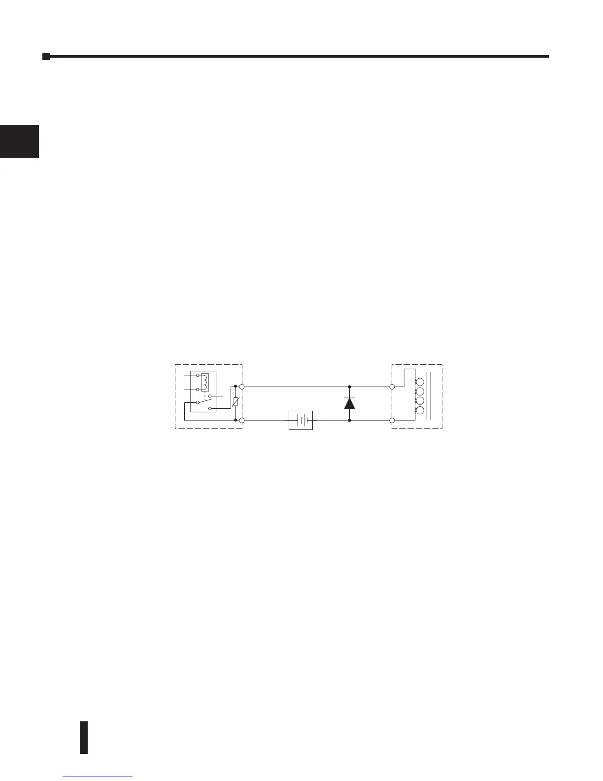
For inductive loads in DC circuits we recommend using a suppression diode as shown in the
following diagram (DO NOT use this circuit with an AC power supply). When the load is
energized the diode is reverse-biased (high impedance). When the load is turned off, energy
stored in its coil is released in the form of a negative-going voltage spike. At this moment the
diode is forward-biased (low impedance) and shunts the energy to ground. This protects the
relay contacts from the high voltage arc that would occur just as the contacts are opening.
Place the diode as close to the inductive field device as possible. Use a diode with a peak inverse
voltage rating (PIV) at least 100 PIV, 3A forward current or larger. Use a fast-recovery type
(such as Schottky type). DO NOT use a small-signal diode such as 1N914, 1N941, etc. Be sure
the diode is in the circuit correctly before operation. If installed backwards, it short-circuits the
supply when the relay energizes.