DL06 Micro PLC User Manual, 3rd Edition, Rev. E
Chapter 2: Installation, Wiring, and Specifications
1
2
3
4
5
6
7
8
9
10
11
12
13
14
A
B
C
D
2-28
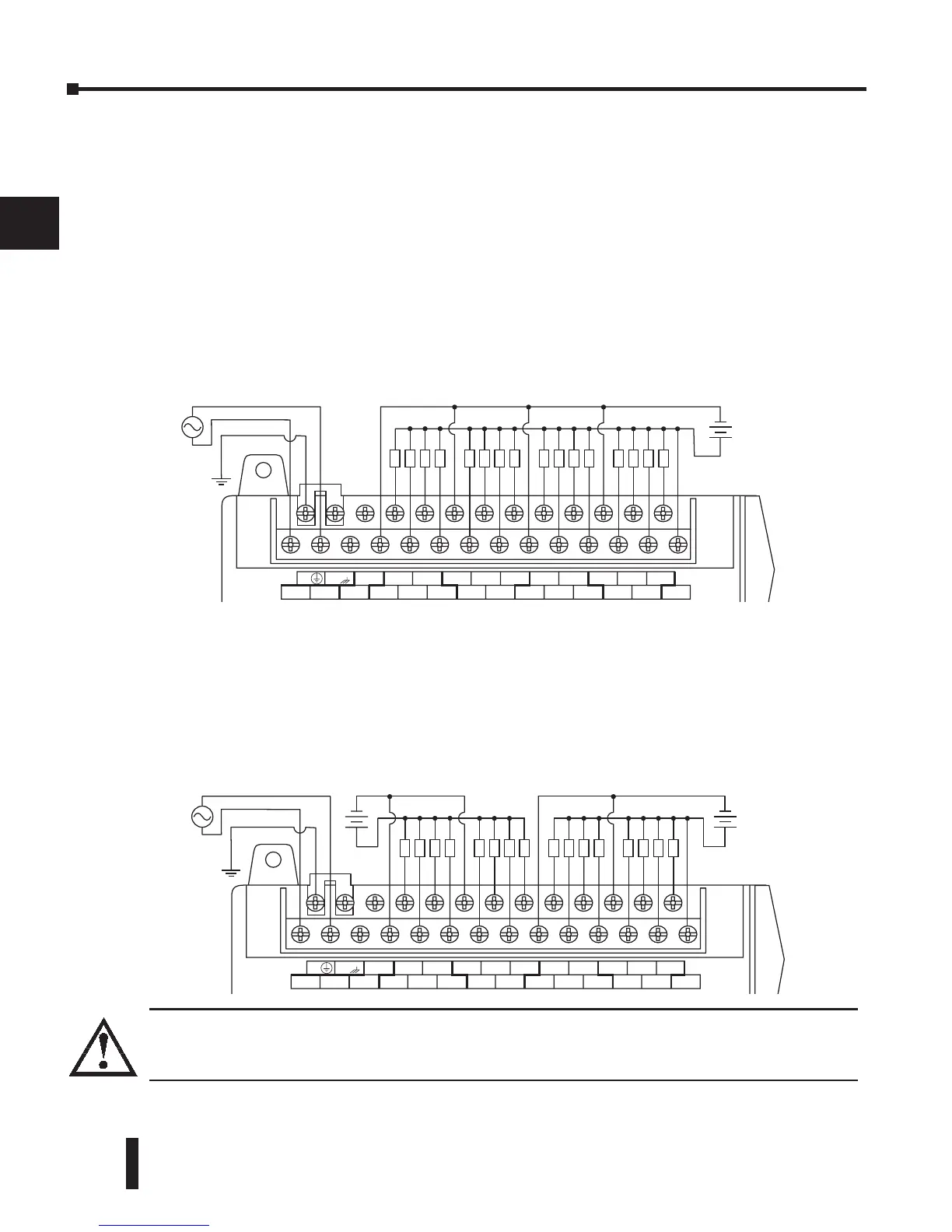
DC Output Wiring Methods
DL06 DC output circuits are high-performance transistor switches with low on-resistance
and fast switching times. Please note the following characteristics which are unique to the DC
output type:
• There is only one electrical common for all sixteen outputs. All sixteen outputs belong to one bank.
• The output switches are current-sinking only or current sourcing only. Refer to the detailed
specifications in this manual to determine which type output is present on a particular model.
• The output circuit inside the PLC requires external power. The supply (–) must be connected to
a common terminal, and the supply (+) connects the right-most terminal on the upper connector
(+V).
In the example below, all sixteen outputs share a common supply.
In the next example below, the outputs have split supplies. The first eight outputs are using a
+12 VDC supply, and the last eight are using a +24VDC supply. However, you can split the
outputs among any number of supplies, as long as:
• all supply voltages are within the specified range
• all output points are wired as sinking
• all source (–) terminals are connected together
Warning: The maximum output current from the Auxiliary 24VDC power depends on the I/O
configuration. Refer to Chapter 4, page 4-6, to determine how much current can be drawn from the
Auxiliary 24VDC power for your particular I/O configuration.