DL06 Micro PLC User Manual, 3rd Edition, Rev. E
Chapter 2: Installation, Wiring, and Specifications
1
2
3
4
5
6
7
8
9
10
11
12
13
14
A
B
C
D
2-34
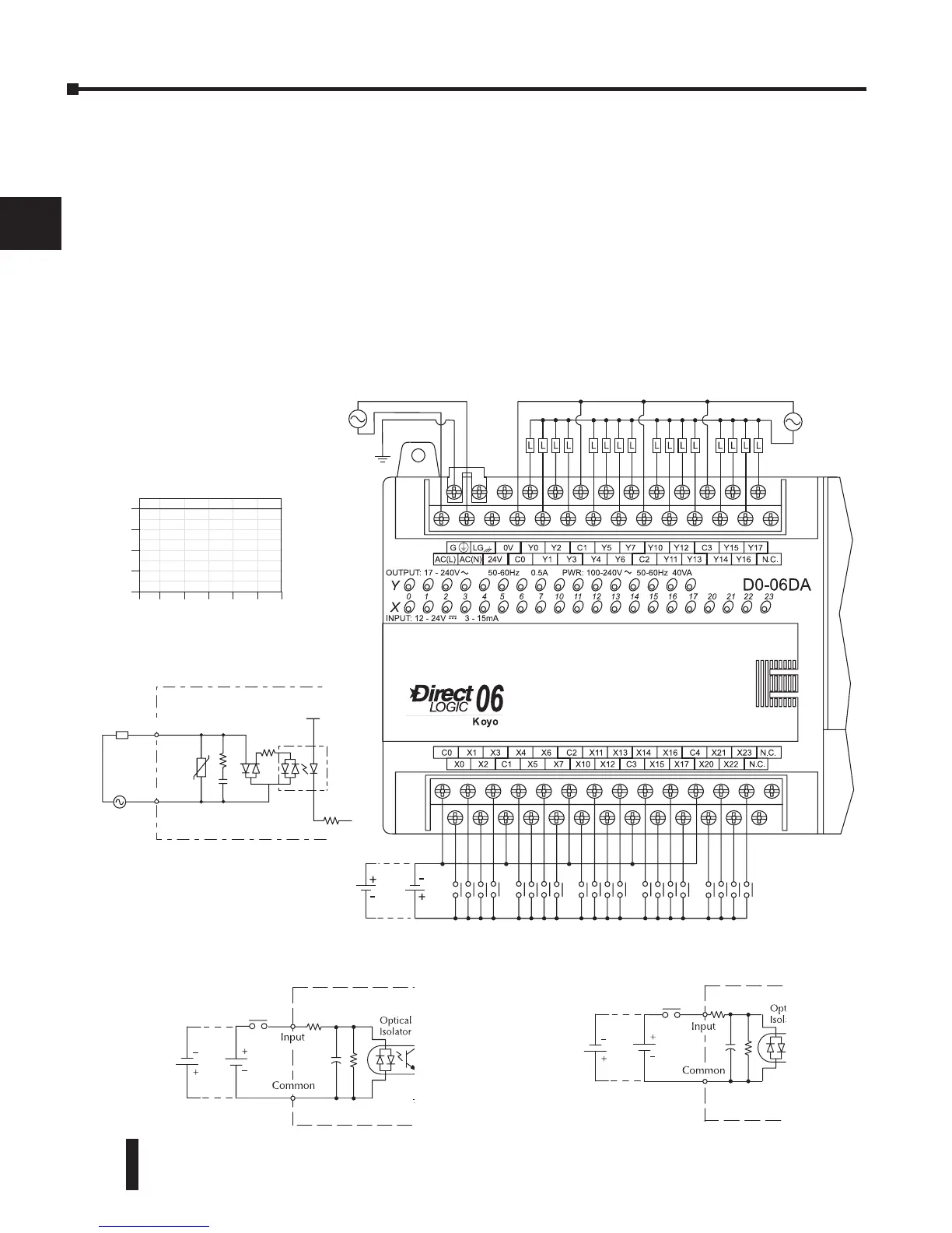
D0–06DA I/O Wiring Diagram
The D0–06DA PLC has twenty DC inputs and sixteen AC outputs. The following diagram shows a
typical field wiring example. The AC external power connection uses four terminals as shown.
Inputs are organized into five banks of four. Each bank has an isolated common terminal, and
may be wired as sinking or sourcing. The wiring example below shows all commons connected
together, but separate supplies and common circuits may be used. The equivalent circuit for
standard inputs is shown below, and the high-speed input circuit is shown to the left.
Outputs are organized into four banks of four triac switches. Each bank has a common terminal. The
wiring example below shows all commons connected together, but separate supplies and common
circuits may be used. The equivalent output circuit shows one channel of a typical bank.
9'&
6LQN6RXUFH
High Speed Inputs (X0-X3)