DL06 Micro PLC User Manual, 3rd Edition, Rev. E
Chapter 2: Installation, Wiring, and Specifications
1
2
3
4
5
6
7
8
9
10
11
12
13
14
A
B
C
D
2-36
Ambient Temperature ( °C/°F)
0
32
10
50
20
68
30
86
40
104
50
122
55°C
131°F
1.0 A
Y0-Y17
8
0.75A
Derating Chart for DC Outputs
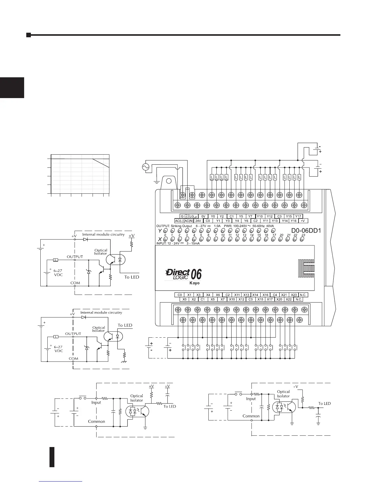
D0–06DD1 I/O Wiring Diagram
The D0-06DD1 PLC has twenty sinking/sourcing DC inputs and sixteen sinking DC outputs. The
following diagram shows a typical field wiring example. The AC external power connection uses four
terminals as shown.
Inputs are organized into five banks of four. Each bank has an isolated common terminal,
and may be wired as either sinking or sourcing inputs. The wiring example below shows all
commons connected together, but separate supplies and common circuits may be used.
Outputs all share the same common. Note the requirement for external power.
Power
input wiring
Input point wiring
Output point wiring
6-27
VDC
20-28
VDC
12-24 VDC
100-240
VAC
SinkSource