DL06 Micro PLC User Manual, 3rd Edition, Rev. E
Chapter 2: Installation, Wiring, and Specifications
1
2
3
4
5
6
7
8
9
10
11
12
13
14
A
B
C
D
2-42
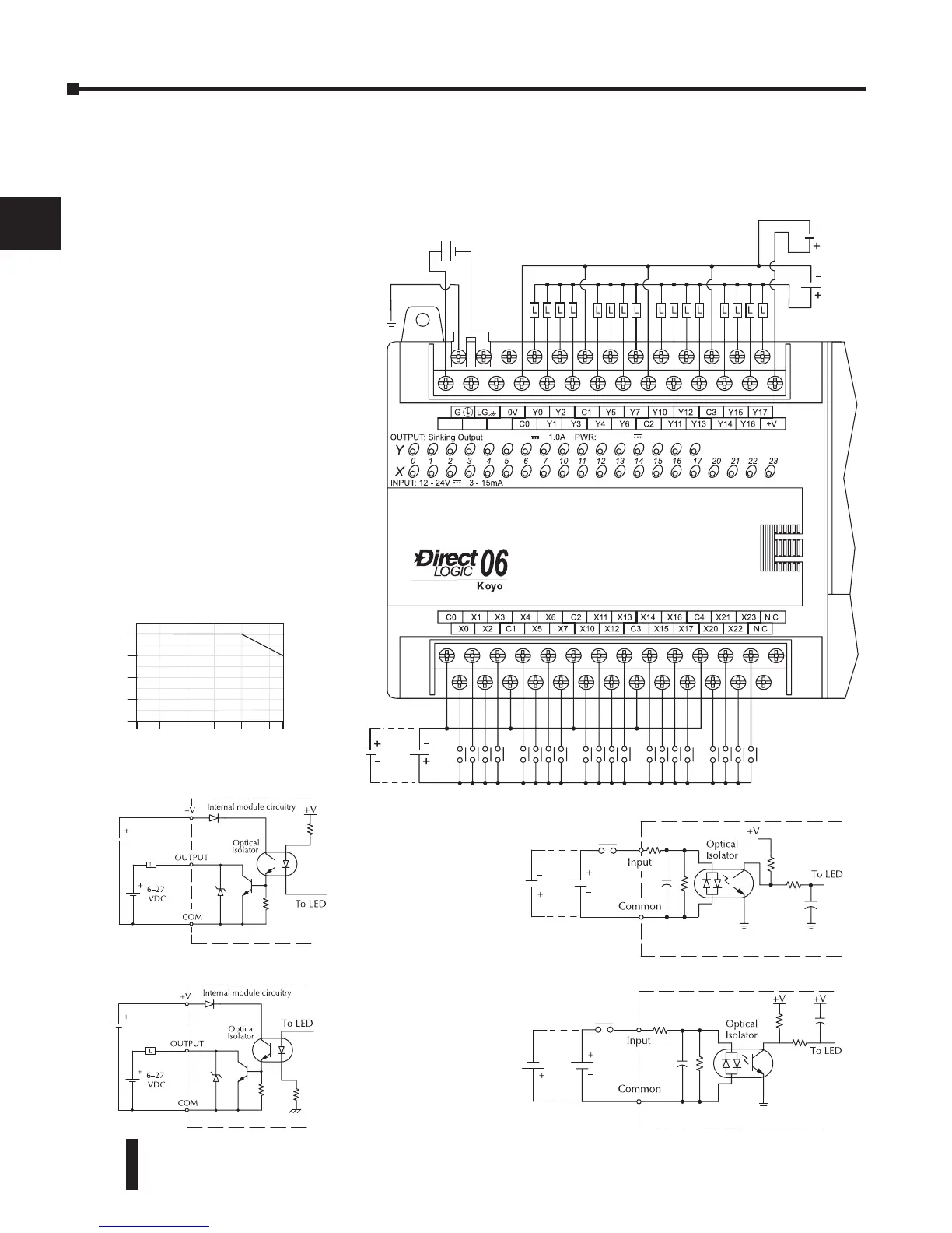
D0–06DD1–D I/O Wiring Diagram
These micro PLCs feature twenty DC inputs and sixteen sinking DC outputs. The following
diagram shows a typical field wiring example. The DC external power connection uses four
terminals at the left as shown.
Inputs are organized into
five banks of four. Each
bank has an isolated
common terminal, and
may be wired as either
sinking or sourcing
inputs. The wiring
example below shows
all commons connected
together, but separate
supplies and common
circuits may be used.
All outputs actually share
the same common. Note
the requirement for
external power.