DL06 Micro PLC User Manual, 3rd Edition, Rev. E
Chapter 2: Installation, Wiring, and Specifications
1
2
3
4
5
6
7
8
9
10
11
12
13
14
A
B
C
D
2-46
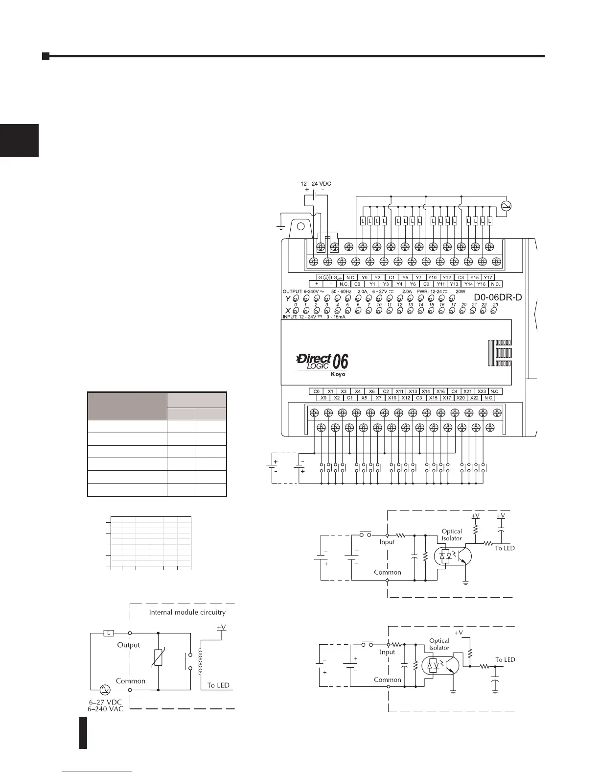
D0–06DR–D I/O Wiring Diagram
The D0–06DR–D PLC has twenty DC inputs and sixteen relay contact outputs. The following
diagram shows a typical field wiring example. The DC external power connection uses three
terminals as shown.
Inputs are organized into five banks of four. Each bank has an isolated common terminal,
and may be wired as either sinking or sourcing inputs. The wiring example above shows all
commons connected together, but separate supplies and common circuits may be used.
Outputs are organized into four
banks of four normally-open relay
contacts. Each bank has a common
terminal. The wiring example above
shows all commons connected
together, but separate supplies and
common circuits may be used. The
equivalent output circuit shows
one channel of a typical bank. The
relay contacts can switch AC or DC
voltages.
Derating Chart for Relay Outputs
High-speed Input Circuit (X0-X3)
9'&
6LQN6RXUFH
Typical Relay Life (Operations) at
Room Temperature
Voltage & Load
Type
Load Current
At 1A At 2A
24VDC Resistive 500K 250K
24VDC Inductive 100K 50K
110VAC Resistive 500K 250K
110VAC Inductive 200K 100K
220VAC Resistive 350K 200K
220VAC Inductive 100K 50K