EasyManua.ls Logo

Autonics BEN Series - User Manual

Autonics BEN Series
6 pages
Print Icon
To Next Page IconTo Next Page
Loading...
A-44
BEN Series
Model BEN10M-TFR BEN5M-MFR BEN3M-PFR BEN300-DFR
Sensing type Through-beam
Retroreective
(Standard type)
Retroreective
(Built-in polarizing lter)
Diffuse reective
Sensing distance 10m 0.1 to 5m
1
0.1 to 3m
1
300mm
2
Sensing target
Opaque materials of
Min. ø16mm
Opaque materials of Min. ø60mm
Translucent,
Opaque materials
Hysteresis
-
Max. 20% at ratedsetting
distance
Response time Max. 20ms
Response time 24-240VAC ±10% 50/60Hz, 24-240VDC ±10%(Ripple P-P : Max. 10%)
Power consumption Max. 4VA
Light source Infrared LED(850nm) Red LED(660nm) Infrared LED(940nm)
Sensitivity adjustment
-
Adjustment VR
Operation mode Selectable Light ON or Dark ON by VR
Control output
Relay contact output
● Relay contact capacity: 30VDC 3A of resistive load, 250VAC 3A resistive load
● Relay contact composition: 1c
Relay lifetime Mechanically: Min. 50,000,000 operation, Electrically: Min. 100,000 operation
Light receiving element Photo IC
Indicator
Operation indicator : red, Stability indicator : green
(The red lamp on Emitter of transmitted beam type is for power indication)
Insulation resistance Min. 20MΩ(at 500VDC megger)
Insulation type Double or strong insulation (Mark :
, Dielectric voltage between the measured input and the power: 1kV)
Noise resistance ±1,000V the square wave noise(pulse width : 1) by the noise simulator
Dielectric strength 1000VAC 50/60Hz for 1minute
Vibration
Mechanical 1.5mm amplitude or 300m/s
2
at frequency of 10 to 55Hz(for 1 min.) in each of X, Y, Z directions for 2 hours
Malfunction 1.5mm amplitude or 300m/s
2
at frequency of 10 to 55Hz(for 1 min.) in each of X, Y, Z directions for 10 minutes
Shock
Mechanical 500m/s²(approx. 50G) in each of X, Y, Z directions for 3 times
Malfunction 100m/s²(approx. 10G) in each of X, Y, Z directions for 3 times
Environ-
ment
Ambient illumination
Sunlight : Max. 11,000㏓, Incandescent lamp : Max. 3,000㏓(Receiver illumination)
Ambient temperature
-20 to 65℃, storage : -25 to 70℃
Ambient humidity
35 to 85%RH, storage : 35 to 85%RH
Protection IP50(IEC standard)
Material ● Case, Case cover: Heat resistant ABS ● Sensing part: PC(with polarizing lter: PMMA)
Cable
ø5, 5-wire, Length: 2m(Emitter of through-beam type: ø5, 2-wire, Length: 2m)
(AWG22, Core diameter: 0.08mm, Number of cores: 60, Insulator out diameter: ø1.25)
Accessory
Individual
-
Reector(MS-2)
-
Common VR adjustment driver, Mounting bracket, Bolts/nuts
Unit weight Approx. 354g Approx. 208g Approx. 195g
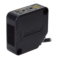
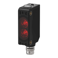
Features
● Small and power supply built-in type
● Easy installation with LED indicators on product
● Enables to set the operation mode by VR
(Light ON/Dark ON)
● Status and output LED indication
● Built-in IC photo diode for ambient light and electrical noise
Compact, amplifier built-in type with Universal voltage
1: The sensing distance is specified with using the MS-2 reflector and same as the MS-4 reflector. Sensing distance is setting range of the
reflector. The sensor can detect under 0.1m
.
2: It is for Non-glossy white paper(100×100mm).
The temperature or humidity mentioned in Environment indicates a non freezing or condensation environment.
● Free power, Relay contact output type
Specifications
MS-4 is sold separately.
(MS-2)
(MS-4)
Please read “Caution for your safety” in operation
manual before using.

Other manuals for Autonics BEN Series

Question and Answer IconNeed help?

Do you have a question about the Autonics BEN Series and is the answer not in the manual?

Summary

Features

Specifications

DC Power, Solid State Output Type

Feature Data

Through-beam Type

Data and characteristics for through-beam sensor models, including parallel shifting.

Retroreflective Type (Standard)

Data and characteristics for standard retroreflective sensors.

Retroreflective Type (Built-in Polarizing Filter)

Data and characteristics for retroreflective sensors with polarizing filters.

Diffuse Reflective Type

Data and characteristics for diffuse reflective sensors.

Operation Mode

Control Output Diagram

Operation Timing Diagram

Connections

Dimensions

Mounting and Sensitivity Adjustment

Through-beam Type Mounting

Guidance on mounting and adjusting through-beam photoelectric sensors.

Retroreflective Type Mounting

Guidance on mounting and adjusting retroreflective photoelectric sensors.

Diffuse Reflective Type Mounting

Guidance on mounting and adjusting diffuse reflective photoelectric sensors.

Retroreflective Type with Polarizing Filter

Details on retroreflective types with polarizing filters and mirror detection.

Overview

The Autonics BEN Series offers compact, amplifier-built-in photoelectric sensors with universal voltage capabilities, designed for versatile industrial applications. These sensors are characterized by their ease of installation, featuring integrated LED indicators for quick status checks and an adjustment VR (Variable Resistor) for setting operation modes (Light ON or Dark ON). Both status and output are clearly indicated by LEDs. A key feature is the built-in IC photodiode, which enhances performance by providing resistance to ambient light and electrical noise, ensuring reliable operation in various environments.

Function Description

The BEN Series encompasses several sensing types:

  • Through-beam (BEN10M-TFR/TDT): Consists of separate emitter and receiver units. Detection occurs when an object interrupts the beam between the two units. Ideal for long-distance detection and precise object positioning.
  • Retroreflective (BEN5M-MFR/MDT, BEN3M-PFR/PDT): Combines the emitter and receiver in a single unit, using a reflector (MS-2 or MS-4) to return the emitted light. An object is detected when it breaks the beam between the sensor and the reflector. The BEN3M-PFR/PDT models include a built-in polarizing filter, which is particularly effective for detecting shiny or reflective objects by preventing false detections from direct reflections.
  • Diffuse Reflective (BEN300-DFR/DDT): Also combines the emitter and receiver in a single unit. Detection occurs when the light emitted from the sensor reflects off the target object and returns to the receiver. Suitable for detecting objects at close range without the need for a separate reflector.

The sensors offer flexible output options:

  • Relay Contact Output (BEN-TFR/MFR/PFR/DFR): Provides a robust relay output suitable for controlling various loads, including AC and DC circuits. This type is powered by universal AC/DC voltage.
  • Solid State Output (BEN-TDT/MDT/PDT/DDT): Features NPN/PNP open collector simultaneous output, ideal for direct interfacing with PLCs and other control systems. This type operates on DC voltage.

Important Technical Specifications

Common Specifications (Universal Voltage Models - Relay Output):

  • Power Supply: 24-240VAC ±10% 50/60Hz, 24-240VDC ±10% (Ripple P-P: Max. 10%)
  • Power Consumption: Max. 4VA
  • Operation Mode: Selectable Light ON or Dark ON by VR
  • Control Output: Relay contact output (1c)
    • Capacity: 30VDC 3A resistive load, 250VAC 3A resistive load
  • Relay Lifetime: Mechanically: Min. 50,000,000 operations; Electrically: Min. 100,000 operations
  • Indicators: Operation (red), Stability (green). Emitter of through-beam type has a red power indicator.
  • Insulation Resistance: Min. 20MΩ (at 500VDC megger)
  • Insulation Type: Double or strong insulation (Dielectric voltage between measured input and power: 1kV)
  • Noise Resistance: ±1,000V square wave noise (pulse width: 1µs) by noise simulator
  • Dielectric Strength: 1000VAC 50/60Hz for 1 minute
  • Vibration: 1.5mm amplitude or 300m/s² at 10-55Hz for 2 hours (mechanical), 10 minutes (malfunction)
  • Shock: 500m/s² (approx. 50G) for 3 times (mechanical), 100m/s² (approx. 10G) for 3 times (malfunction)
  • Ambient Illumination: Sunlight: Max. 11,000lx; Incandescent lamp: Max. 3,000lx (Receiver illumination)
  • Ambient Temperature: -20 to 65°C (operation), -25 to 70°C (storage)
  • Ambient Humidity: 35 to 85%RH (operation), 35 to 85%RH (storage)
  • Protection: IP50 (IEC standard)
  • Material: Case/Cover: Heat resistant ABS; Sensing part: PC (with polarizing filter: PMMA)
  • Cable: Ø5, 5-wire, Length: 2m (Through-beam emitter: Ø5, 2-wire, Length: 2m)
    • AWG22, Core diameter: 0.08mm, 60 cores, Insulator outer diameter: Ø1.25
  • Unit Weight: Approx. 354g (BEN10M-TFR), 208g (BEN5M-MFR), 195g (BEN300-DFR)

Common Specifications (DC Power Models - Solid State Output):

  • Power Supply: 12-24VDC ±10% (Ripple P-P: Max. 10%)
  • Current Consumption: Max. 50mA
  • Control Output: NPN open collector / PNP open collector simultaneous output
    • Load Voltage: Max. 30VDC; Load Current: Max. 200mA
    • Residual Voltage: NPN: Max. 1V; PNP: Max. 2.5V
  • Protection Circuit: Reverse polarity protection, Short-circuit protection
  • Unit Weight: Approx. 342g (BEN10M-TDT), 200g (BEN5M-MDT), 187g (BEN300-DDT)

Specific Sensing Distances and Targets:

  • BEN10M-TFR/TDT (Through-beam): 10m; Opaque materials of Min. Ø16mm. Light source: Infrared LED (850nm).
  • BEN5M-MFR/MDT (Retroreflective): 0.1 to 5m (with MS-2 reflector); Opaque materials of Min. Ø60mm. Light source: Red LED (660nm).
  • BEN3M-PFR/PDT (Retroreflective with polarizing filter): 0.1 to 3m (with MS-2 reflector); Opaque materials of Min. Ø60mm. Light source: Red LED (660nm).
  • BEN300-DFR/DDT (Diffuse Reflective): 300mm (for non-glossy white paper 100x100mm); Translucent, Opaque materials (Max. 20% at rated setting distance). Light source: Infrared LED (940nm).

Usage Features

  • Easy Installation: The compact design and built-in amplifier simplify mounting and wiring. LED indicators on the product provide immediate feedback on operation and stability, reducing setup time.
  • Operation Mode Selection: A VR adjustment allows users to easily switch between Light ON (output turns ON when light is received) and Dark ON (output turns ON when light is interrupted) modes, adapting to various application requirements.
  • Sensitivity Adjustment: A dedicated VR is provided for sensitivity tuning, especially crucial for diffuse reflective types to optimize detection based on target characteristics and mounting conditions.
  • Reflector Options: For retroreflective models, MS-2 reflectors are standard, with MS-4 available for tighter mounting spaces.
  • Ambient Light/Noise Immunity: The built-in IC photodiode provides enhanced resistance to external light interference and electrical noise, ensuring stable detection in challenging industrial environments.
  • Polarizing Filter (BEN3M-PFR/PDT): This feature is critical for applications involving highly reflective surfaces, preventing false detections by filtering out direct reflections from the target. The light from the emitter is horizontally polarized, reflects off the MS-2 reflector, becoming vertically polarized, and is then detected by the receiver.
  • Output Protection: DC models include reverse polarity protection and short-circuit protection, safeguarding the sensor and connected equipment from electrical faults.

Mounting and Sensitivity Adjustment Guidelines:

  • Through-beam Type:
    1. Mount emitter and receiver facing each other.
    2. Adjust the receiver's position to the center of the stability range (indicated by the LED).
    3. Verify stable operation by introducing the target at the optical axis.
    4. Note: Translucent objects or objects smaller than Ø16mm may cause light penetration and missed detections.
  • Retroreflective Type:
    1. Mount the sensor and reflector (MS-2) face-to-face.
    2. Adjust the sensor's position until the indicator turns ON, optimizing detection by adjusting the reflector or sensor.
    3. Secure both units after confirming target detection.
    4. For multiple sensors, maintain a minimum spacing of 30cm to prevent interference.
    5. For highly reflective targets, position the target at a 30° to 45° angle relative to the sensor or use a polarizing filter model (BEN3M-PFR/PDT) to prevent false detections.
  • Diffuse Reflective Type:
    1. Place the target at the desired detection point.
    2. Turn the adjustment VR from minimum until the operation indicator turns ON (position 'a').
    3. Remove the target and turn the VR until the indicator turns ON again (position 'b'). If it doesn't turn ON, 'b' is at the maximum VR position.
    4. Set the VR to the center of 'a' and 'b' for optimal sensitivity.
    5. Sensing distance is specified for 100x100mm non-glossy white paper and may vary based on target size, surface, and gloss.

Maintenance Features

  • Durable Construction: The use of heat-resistant ABS for the case and cover, along with PC for the sensing part, ensures robustness and longevity in industrial environments.
  • High IP Rating: An IP50 protection rating signifies resistance to dust ingress and protection against accidental contact, contributing to reliable operation and reduced maintenance needs.
  • Long Lifespan: The mechanical and electrical relay lifetimes (for relay output models) are designed for extended operation, minimizing the frequency of replacements.
  • Clear Indicators: The red (operation) and green (stability) LEDs provide clear visual cues for troubleshooting and monitoring sensor status, simplifying maintenance tasks.
  • Standard Accessories: Each sensor includes a VR adjustment driver, mounting bracket, and bolts/nuts, facilitating initial setup and potential re-installation.

Autonics BEN Series Specifications

General IconGeneral
BrandAutonics
ModelBEN Series
CategoryAmplifier
LanguageEnglish

Related product manuals