EasyManua.ls Logo

Autonics BF5 Series - User Manual

Autonics BF5 Series
15 pages
To Next Page IconTo Next Page
Loading...
B-9
(A)
Photo
electric
sensor
(B)
Fiber
optic
sensor
(C)
Door/Area
sensor
(D)
Proximity
sensor
(E)
Pressure
sensor
(F)
Rotary
encoder
(G)
Connector/
Socket
(H)
Temp.
controller
(I)
SSR/
Power
controller
(J)
Counter
(K)
Timer
(L)
Panel
meter
(M)
Tacho/
Speed/ Pulse
meter
(N)
Display
unit
(O)
Sensor
controller
(P)
Switching
power
supply
(Q)
Stepping
motor&
Driver&Controller
(R)
Graphic/
Logic
panel
(S)
Field
network
device
(T)
Software
(U)
Other
Specifications
The temperature or humidity mentioned in Environment indicates a non freezing or condensation environment.
BF5 Series Fiber Optic Amplier
Please read “Caution for your safety” in operation
manual before using.
Dual digital display type fiber optic amplifiers
Features
● Dual-display for light incident level and setting value(BF5 -D)
● Minute object sensing available with 1/10,000 high resolution
● Enables to detect with high-speed(20,000 times per sec.) moving objects
● 4 response speeds
: Ultra fast mode(50
), high speed mode(150
),
standard mode(500
), long distance mode(4ms)
● Long lasting amplifier regardless of element’s life degradation
or temperature change
● Multiple sensitivity setting modes available
: auto tuning, 1 point(maximum sensitivity), 2 point, positioning teaching
● Up to 8 units enable to stack with mutual interference prevention function
using side connectors
Auto channel setting function for multiple installations
● Slim design(W10×H30×L70mm)
Model
Display type Dual Display type Single Display type
NPN open collector output
BF5R-D1-N BF5G-D1-N BF5B-D1-N BF5R-S1-N
PNP open collector output
BF5R-D1-P BF5G-D1-P BF5B-D1-P BF5R-S1-P
Light source
Red LED
(660nm, modulated)
Green LED
(530nm, modulated)
Blue LED
(470nm, modulated)
Red LED
(660nm, modulated)
Power supply 12-24VDC±10%
Current consumption Max. 50mA
Operation mode Light ON / Dark ON Selectable
Control output
NPN or PNP open collector
●Load voltage: Max. 24VDC ●Load current: Max. 100mA ●Residual voltage
-
NPN:Max. 1V, PNP:Max. 3V
Protection circuit Reverse polarity protection, overcurrent protection, surge absorption
Response time Ultra Fast : 50
, Fast : 150
,STD : 500
, Long : 4ms Fast : 150
, STD : 500
, Long : 4ms
Display method
●Incident light level: Red, 4digit, 7Segment
●SV : Green, 4digit, 7Segment
●Main output indicator : Red LED
●Incident light level / SV : Red, 4digit, 7Segment
●Main output indicator : Red LED
Display function
Incident light level / SV display [4,000/10,000 resolution], Percentage display, High/Low peak value display,
Normal / Reversed display
Sensitivity setting
Auto tuning, 1 point teaching,
2 point teaching, Positioning teaching
Auto tuning
Mutual interference
prevention
Max. 8 unit sets (Automatically set regardless of response time)
Initializing Initializing to factory mode
-
Energy saving Normal / Energy saving 1 / Energy saving 2
-
Timer OFF, OFF Delay, ON Delay, One-shot OFF, 10ms OFF Delay timer, 40ms OFF Delay timer
Insulation resistance Min. 20MΩ(at 500VDC megger)
Dielectric strength 1,000VAC 50/60Hz for 1 min.
Vibration 1.5mm amplitude at frequency of 10 to 55Hz(for 1 min.) in each X, Y, Z directions for 2 hours
Shock 500m/s
2
(Approx. 50G) in each X, Y, Z directions for 3 times
Environ-
ment
Ambient illumination
Incandescent lamp : Max. 3000
Sunlight : Max. 11000
Ambient temperature
-10 to 50
, storage: -20 to 70
Ambient humidity
35 to 85%RH, storage: 35 to 85%RH
Protection IP40(IEC standards)
Material Case : PBT, Cover : PC
Fiber cable
Tightening torque
Min. 2kgf
Accessory
Connector type wire(ø4, 3-wire, 2m) (AWG22, Core diameter: 0.08mm, Number of cores: 60,
Insulator out diameter: ø1.25mm), Side connector
Approval
Unit weight Approx. 20g
Line-up
PNP output model

Other manuals for Autonics BF5 Series

Question and Answer IconNeed help?

Do you have a question about the Autonics BF5 Series and is the answer not in the manual?

Autonics BF5 Series Specifications

General IconGeneral
BrandAutonics
ModelBF5 Series
CategoryAmplifier
LanguageEnglish

Summary

Features

Specifications

Control Output Diagram

Dimensions and Installation

Dimensions

Provides physical measurements of the BF5 amplifier units.

Installations

Instructions for mounting the amplifier unit on a DIN rail and connecting units.

Connection and Operation Modes

Fiber and Wire Connector Connection

Guides for connecting fiber optic cables and wire connectors to the amplifier.

RUN Mode Operation

Overview of the normal operating mode and basic key functions.

Sensitivity Setting Modes

Manual Sensitivity Setting

Sets sensitivity manually and is used for fine-adjustment after teaching.

Teaching Sensitivity Setting

Covers Auto-tuning, One-point, Two-point, and Positioning teaching methods.

One-point Teach Mode

Two-point Teach Mode

Positioning Teach Mode

Ground Teach Mode

Master;Slave Unit Communication

Group Teach Mode Display

Shows display status during group teaching between master and slave units.

Program Mode Introduction

Program Mode Flow

Illustrates the sequence for accessing and navigating program mode settings.

Program Mode Functions

Response Time Setting

Selects control output response time (Ultra Fast, Fast, Standard, Long distance).

Display Function Selection

Configures incident light level display mode (Standard/Percentage).

Timer Functionality

Sets timer operations (OFF Delay, ON Delay, One-shot) and time settings.

Unit Functions

Energy Saving Function

Reduces power consumption by dimming displays when inactive.

Light;Dark ON Switching

Sets output to activate on high (Light ON) or low (Dark ON) incident light levels.

Lock Function

Prevents accidental changes to sensitivity, mode, or initialization settings.

Data Bank Settings

Manages saving and loading of multiple configuration sets for different sensing objects.

Data Bank Mode Operations

Data Load and Save

Loads preset data or saves current settings to/from data banks.

Data Copy Operations

Copies data banks between units (1:1, 1:M) or loads/saves all units.

Data Bank Master;Slave Display

Copy, Load, Save All Operations

Shows display status during Copy All, Load All, and Save All data bank operations.

Peak Value Monitoring and Initialization

High;Low Peak Value Function

Monitors and displays the highest and lowest incident light levels detected.

Parameter Initialize Flow

Resets all parameters to factory defaults to prevent misoperation.

Sensitivity Setting Mode Overview

Auto Tuning Sensitivity

Core Functions Overview

Response Time Setting (Front Switch)

Sets response time via front slide switch (Fast, Standard, Long distance).

Display Function Selection

Chooses display mode for incident light level (standard/percentage).

Timer Function Modes

Configures timer operations like OFF Delay, ON Delay, and One-shot.

Group Teaching

Side Connector and Channel Settings

Amplifier Unit Connection

Details connecting multiple units via side connectors for shared power.

Auto Channel Setting

Automatically sets channels for connected units when power is supplied.

Interference Prevention and Error Handling

Mutual Interference Prevention

Prevents interference between adjacent units by setting different receiving times.

Error Code Troubleshooting

Lists error codes, their causes, and corresponding troubleshooting steps.
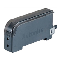
Related product manuals