Page 02 KKCTE02T-A/0-20131221
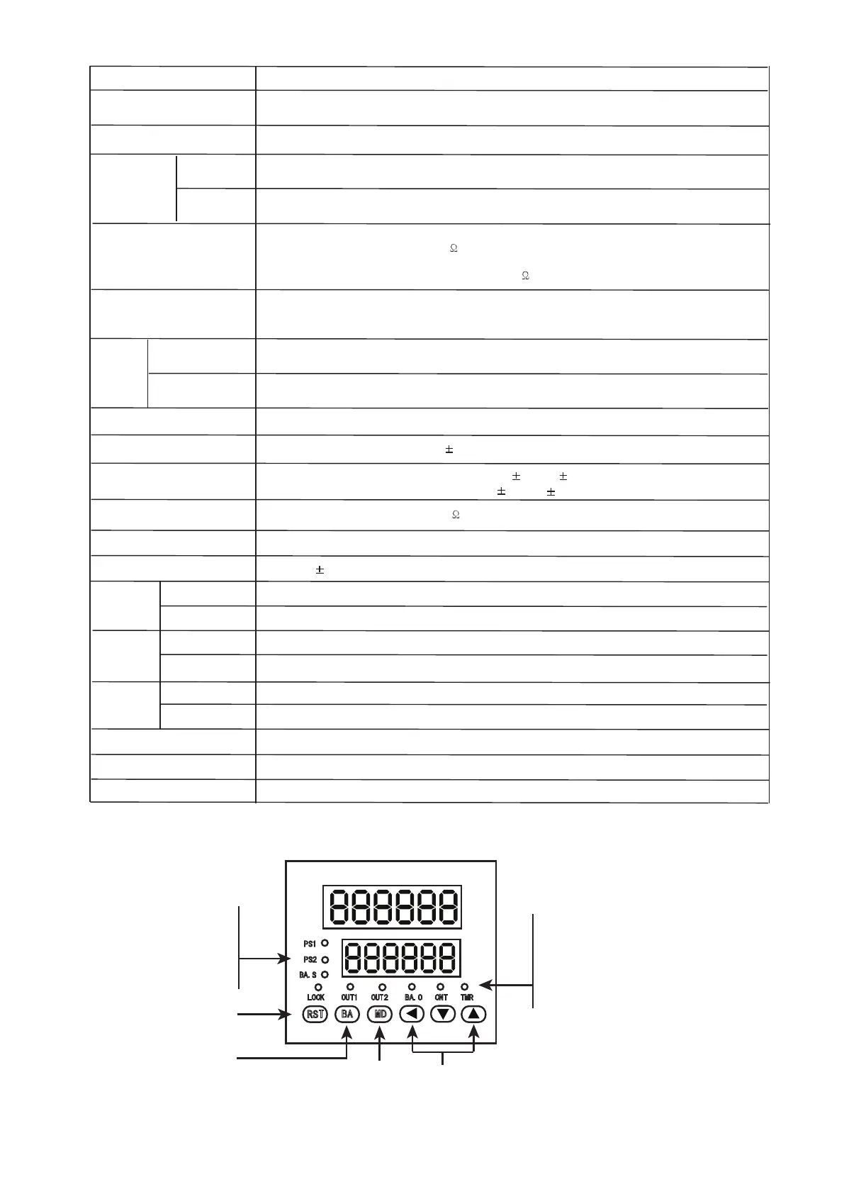
3.Panel Indication
Reset
Batch setting key
Function key
Parameter modifying key
PS1: Indicate that setting value of OUT1
BA.S:Above LED display batch counting value
Lock: (CT16,CT8 without indicate light)
OUT1,OUT2: OUT1 or OUT2 output indicate
BA.0 :Batch output indicate(CT3,CT4 without indicate light)
CNT: Counting mode
TMR:Timing mode
PS1
PS2
BA.S
LOCK OUT1 OUT2 BA.0 CNT TMR
RST
BA MD
being displayed on the below LED
PS2: Indicate that setting value of OUT2
being displayed on the below LED
Below LED display batch setting value
Key lock indication
2. Technical Specification
-10 ~ +50
Selectable voltage input or Non-voltage input
Voltage input : Input impedance:5.4k , H level :5 -30VDC, L level: 0-2VDC, L level: Max.2VDC,
Non -voltage input :Short-circuit impedance:Max.1k,Residual voltage:Max.2VDC,
OPen-circuit impedance:Min.100k
Power Supply
Allowable Voltage Range
90~110% of rated voltage(AC power)
Reset input: Selectable 1ms or 20ms
Min.input
Signal width
Counter
Timer
Input
One-shot output
10/50/100/200/500/1000/2000/5000ms
Control
Output
Contact Point
Capacity
NO:250VAC 3A at resistive load, NC:250VAC 2A at resistive load
Solid State Relay
Capacity
~
+65
~
INA, INHIBIT, RESET, BATCH RESET: Selectable 1ms or 20ms
100-240V AC/DC
INA INB input frequency
1Hz, 30Hz, 1KHz , 5KHz ,10KHz are selectable
℃ (at non-freezing status)
℃(at non-freezing status)
Timing Accuracy
Power on start accuracy:
0.05%
Signal start accuracy :
0.05sec
0.05%
0.03sec
External sensor power
12V DC
10%, Maximum 100mA
Memory time
memory datasheet for 10 years
Insulation resistance
Min 100M
( at 500V DC)
Dielectric Strength
2000V AC 50/60Hz 1minute
Anti-interfere
2kV , the square wave generator interference ( pulse width: 1uS)
Max. 30VDC , Max. 100mA
Vibration
Shock
Relay
life cycle
Mechnical
amplitude : 0.75mm , frequency : 10 55Hz, X , Y , Z directions each for 1 hour
amplitude: 0.5mm , frequency:10 55Hz , X , Y , Z directions each for 10 minutes
~
Malfunction
Mechnical
Malfunction
Mechnical
Electrical
more than 10,000,000 times
More than 100,000 times , (NO: 250VAC 3A load , NC: 250V AC 2A load)
300/S
2
( about: 30G) X , Y , Z directions for 3 times each
100/S
2
( about: 10G) X , Y , Z directions for 3 times each
Work temperature
Storage temperature
Storage humidity
35 85%RH
 Loading...