Do you have a question about the Autonics LP-A070 Series and is the answer not in the manual?
Details user screen design and LP-A070 HMI function usage.
Covers atLogic installation, usage, programming, and LP Series commands.
Explains connection with external devices like PLCs.
Provides general information on LP-A070 installation and system.
Details power supply, interfaces, environmental resistance, and approval.
Covers LCD type, resolution, display area, color, view angle, and luminance.
Details language support, text, graphic memory, user screen count, and touch type.
Lists interfaces for LP-A070-T9D6-C5R(T) and LP-A070-T9D7-C5R(T).
Specifies input points, insulation, voltage, resistance, and response time.
Details output points, power supply, insulation, load voltage, and current.
Covers command structure, program capacity, processing time, and I/O control.
Details graphical elements like figures, lamps, switches, text, graphs, and objects.
Covers project management, editing, tools, online operations, debugging, and workspace.
Explains LED colors and statuses for program execution and debugging.
Details pin assignments for RS232C and RS422 serial ports.
Describes Ethernet port usage for LAN and PC connections.
Outlines USB Host and USB Device functions like data transfer and firmware upgrades.
Provides dimensions for panel cut-out and fixing bracket mounting.
Shows input (source) and output (sync) wiring for LP-A070-T9D6(7)-C5R.
Details input (source) and output (sync) wiring for LP-A070-T9D6(7)-C5T.
Guidance on panel installation, bracket fixing, and required surrounding space.
Specifies wire cross-section, terminal type, polarity, and grounding.
Notes that communication cables are sold separately and refer to manuals.
Advises contacting service for battery replacement due to safety risks.
Lists important safety precautions for operation, environment, and touch panel.
The LP-A070 Series represents an advanced 7-inch color LCD logic panel, designed as an all-in-one solution integrating PLC, HMI, and I/O functionalities. This design aims to simplify system configuration and use, while also offering greater flexibility in installation locations.
The device serves as a comprehensive control and monitoring interface for various industrial applications. Its core function is to provide a visual and interactive platform for managing connected controllers and processes. The LP-A070 is equipped with a 7-inch TFT LCD, capable of displaying 16,777,216 colors, ensuring a true-color visual experience. The resistive touch screen allows for interaction using a finger, glove, or pen tip, enhancing usability in diverse industrial environments.
For communication, the panel supports a variety of interfaces including RS232C, RS422, and Ethernet, enabling seamless integration with external devices such as PCs, PLCs, serial printers, and barcode readers. It features standard I/O with 16 input points and 16 output points, providing direct control capabilities.
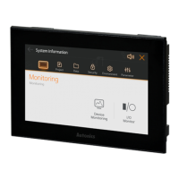
A key feature is its ability to simultaneously monitor multiple addresses and channels of connected controllers, even without pre-loaded user screen data. This allows for immediate oversight of system status. The device also incorporates a multilingual table function, enabling users to switch the language of the user screen with a simple touch, catering to international operational needs.
The LP-A070 includes a real-time controller (RTC) and supports motion controller and high-speed counter functions, expanding its application scope to more dynamic control tasks. Its large capacity memory, including 64MB for user screens, allows for the storage of complex graphical interfaces and extensive data.
The LP-A070 is designed for intuitive operation and flexible deployment. Users can install the panel either horizontally or vertically, adapting to the specific spatial constraints and environmental requirements of the installation site.
The device leverages a user screen drawing program called 'atDesigner'. This software facilitates the creation of user interfaces with a wide array of functions, objects, and library images, promoting a more intuitive and visually rich user experience. The 'atDesigner' user manual provides detailed instructions on designing user screens and utilizing the HMI functions of the LP-A070.
For programming logic, the 'atLogic' software is provided. The 'atLogic' user manual and programming manual guide users through installation, programming, and command usage for the LP Series, enabling the development of custom control logic.
The GP/LP user manual for communication offers comprehensive information on connecting the LP-A070 with external devices like PLCs, ensuring proper setup and data exchange. The LP-A Series user manual provides general information regarding the installation and overall system of the LP-A070.
The graphical drawing performance supports Korean and English languages, with the capability to add more. It utilizes bitmap ASCII and vector fonts for text display. The device can store up to 100 pages of user screens, offering ample space for complex applications. The analog resistive touch switch ensures reliable interaction.
The USB interface supports both Host and Device modes. In USB Host mode, it facilitates transferring/copying data between storage and the LP-A070, firmware upgrades, and connection of barcode readers or printers. In USB Device mode, it allows for uploading/downloading 'atDesigner' project files and can be used as external storage when connected to a PC. The USB Host can accommodate up to 32GB of external storage, supporting FAT16 and FAT32 file systems.
The drawing function includes various graphical elements such as lines, rectangles, circles, and images, along with text display. It supports multi-lamp displays for device values, and various switch types (bit, word, change screen, special, multi) for controlling devices or objects. Numeric input/display allows for showing and inputting values in different formats (DEC, HEX, OCT, BIN, REAL). Text input/display supports ASCII/Unicode.
Advanced display features include call windows, messages, and graphs (bar, pie, panel meter, trend, distribution) for comprehensive data visualization. A clock function displays time or date. Recipe editing, logging tables (system and alarm), and alarm explorers provide robust data management and historical tracking. Data list viewers/editors and option lists enhance data manipulation. The 'Move coord.' function allows for dynamic object positioning based on device values.
The 'Link device' function enables data reading and writing between the LP and a controller (PLC) based on set conditions. Flow alarms display messages when alarming conditions are met, and alarm history records alarming events. The scheduler executes functions based on device or cycle conditions. Logging capabilities include saving device values and system operation information, while Lua script writing offers advanced customization.
The logic function supports project creation and management, including changing PLC types and print settings. The ladder/mnemonic editor facilitates program development with features like line management, rung searching, and step finding. A comprehensive set of ladder tools (contacts, coils, instructions) is available. Program optimization and checking tools ensure code quality.
The view function allows users to switch between ladder/mnemonic views, manage device/variable names, and adjust display settings like zoom, font, and color. Online functions enable connecting, downloading, uploading, changing mode, monitoring, and reading information. Debugging features include run/stop, trace, breakpoint management, step-by-step debugging, and forced I/O settings.
The LP-A070 is designed with consideration for ease of maintenance. The battery, which has a life cycle of 3 years at 25°C, can be replaced by contacting the service center. This ensures the longevity of the real-time clock and other battery-dependent functions.
The installation process is straightforward, involving setting the LP-A070 into a panel and securing it with fixing brackets. The instruction manual specifies a tightening torque for the screws to ensure proper installation. Adequate spacing (100mm) around the unit is recommended to prevent electromagnetic interference and heat accumulation from other controllers.
Power wiring guidelines specify the use of wires with appropriate cross-sections (0.75mm² for power, 1.25mm² for grounding) and round terminals. It emphasizes checking power polarity and tightening terminal screws to a specified torque. Ground resistance should be less than 1000Ω.
Safety considerations are paramount. Users are advised to follow all instructions in the manual to prevent accidents. The 24VDC power supply should be insulated and meet Class 2, SELV standards. An easily accessible power switch or circuit breaker is recommended. The product should only be operated after power is supplied to all connected equipment.
To prevent inductive noise, the device should be kept away from high voltage lines or equipment generating strong magnetic fields or high-frequency noise. Proper ventilation is crucial, and openings should not be blocked. The touch panel should be handled with care, avoiding hard or sharp objects and excessive force to prevent damage. In case of LCD breakage and liquid crystal exposure, immediate rinsing with water and medical attention are advised.
The unit is designed for indoor use within specified environmental conditions, including an altitude of up to 2,000m, pollution degree 2, and installation category II.
| Display Type | 7-segment LED |
|---|---|
| Digits | 4 |
| Power Supply | 24 VDC ±10% |
| Protection Structure | IP65 (front panel) |
| Storage Temperature | -20 to 60 °C |