LP-A070 Series
V-28
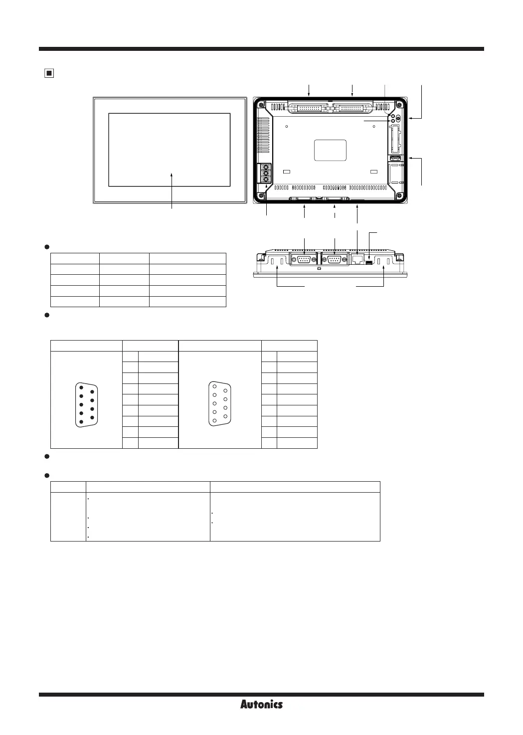
Unit Description
Program status LED
LED color LED status Program status
Green ON Run
Green Flashing Pause
Red Flashing Error
Orange ON atLogic debugging
Serial port (RS232C/RS422)
All devices connectable to the product including PC, PLC, serial printer, barcode reader, and dedicated connectors can
be connected in to both RS232C and RS422 ports.
Port Pin Port Pin
RS232C
RS232C-A
RS232C-B
9
8
7
6
5
4
3
2
1
D-Sub 9-pin Male
1 Non-Used
RS422
6
7
8
9
1
2
3
4
5
D-Sub 9-pin Female
1 TXD+
2 RXD 2 RXD+
3 TXD 3 Non-Used
4 DTR 4 Non-Used
5 SG 5 SG
6 DSR 6 TXD-
7 Non-Used 7 RXD-
8 Non-Used 8 Non-Used
9 Non-Used 9 Non-Used
Ethernet port
For connecting LAN cable and hub, use direct cable, and for connecting PC directly, use cross cable.
USB
Type USB Host USB Device
Function
Transferring/Copying data between
storage and LP-A070
Firmware upgrade
Bar-code reader
Printer
Uploading/Downloading a atDesigner project file
Used as external storage by connecting to PC
USB HOST can cover up to 32GB of external storage.
It supports only external storage of FAT16 and FAT32 file system.
※
For detailed information about each interface, please refer to 'LP-A Series user manual' and 'GP/LP Communication
manual'.
LCD Screen
Input
terminal
Output
terminal
Power
LED
Run/Stop
Switch
Power
terminal
RS422
or
RS232C-A
RS232C
or
RS232C-B
Ethernet
USB
Device
USB
Host
Mounting slot
for bracket
Program
status LED
 Loading...