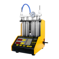
The AUTOOL CT150/CT200 Fuel System Cleaner is a mechatronic product that combines ultrasonic cleaning technology with microprocessor oil pressure control for cleaning and detection. This device is designed to simulate various engine working conditions, clean, and inspect car fuel injectors, and can also be used for cleaning and disassembling fuel injectors and the fuel supply system.
Function Description:
- Ultrasonic Cleaning: This function performs simultaneous cleaning on multiple injectors, effectively removing carbon deposits. The ultrasonic cleaning process utilizes penetration and cavitation shock waves generated by ultrasonic waves propagating in a medium. This allows for strong cleaning of objects with complex shapes, inner cavities, and fine pores, completely removing stubborn carbon from the injector.
- Uniformity/Sprayability Test: This test assesses the uniformity of the injecting amount for each injector and monitors their spraying status with the aid of a backlight. It also supports reverse flush. The uniformity test detects whether the difference between the injection quantities of injectors meets specified requirements or falls within the error range under identical working conditions for injectors on the same vehicle. This inspection reveals the electrical characteristics of the injector, changes in nozzle diameter, and the combined effects of plugging and other factors. The atomization test evaluates the injector's atomization performance by observing its injection condition and atomization under specific working conditions.
- Leakage Test: This function checks the sealing and dribbling conditions of injectors under system pressure.
- Injecting Flow Test: This test measures the injecting amount of an injector over 15 seconds of constant injection.
- Automatic Test: This mode allows for testing injectors by simulating various working conditions automatically.
- On-Vehicle Cleaning: The unit comes with various adaptors and couplers to facilitate cleaning injectors directly on the vehicle.
- Fuel Pressure Control: Microcomputer-controlled fuel pressure offers stable and widely adjustable pressure, making it suitable for all EGI (Electronic Gasoline Injection) vehicles. This enables automatic cleaning and testing of injectors.
- Microcomputer Control and Digital Display: These features enable automatic cleaning and testing, along with real-time monitoring of dynamic values.
- Automatic Fuel Draining: For some test items, fuel or detergent is drained automatically through preset programs. After a test, it can also be drained by pressing a button on the control panel.
- Humanized Design: This design ensures that the system pressure is quickly restored to default values.
Important Technical Specifications:
Working Conditions:
- Power Supply: AC220V±10% (for CT200), AC220V/AC110V±10% 50Hz/60Hz (for CT150)
- Frequency: 50HZ±0.5
- Ambient Temperature: -10 °C ~ +40 °C
- Relative Humidity: <85%
- External Magnetic Field Strength: <400A/m
- Open Flames: Strictly prohibited within 2m
Device Specifics:
- Fuel Tank Capacity: 2000 ml
- Capacity of Measuring Cylinder: 125 ml
- Speed Range: 0~7500 rpm
- Injecting Times: 0~9900 (Step: 100ms)
- PWM Pulse: 0~20.0 ms (Step: 0.1 ms)
- System Pressure: 0~0.6Mpa (adjustable)
- Time: 0~20 minute (adjustable)
- Power of Ultrasonic Cleaning: 70W
- Frequency of Ultrasonic Cleaning: 28 KHZ±0.5 KHZ
- Input Power: 250W
- Timing Range: 1 to 9999 seconds
- Pulse Width Range: 0.5 ~ 25ms (Step size 0.1ms)
Usage Features:
- Preparation: Before operation, users must read the manual carefully. Key steps include removing the injector, checking for damage, putting the nozzle into gasoline or detergent, cleaning the external oil, checking the fuel filter port, adding cleaning liquid, and selecting the correct injector connection coupler.
- Injector Installation (Up-inlet): This involves selecting the appropriate oil separator and "O" ring, applying grease, installing the plug, tightening the crescent-shaped pressure plate, selecting the correct straight oil connector, installing the injector in the forward direction (with grease on the "O" ring), selecting and installing the adjusting screw and knurled nut, and finally tightening the two knurled screws. The injector pulse signal line is then inserted.
- Injector Installation (Side-inlet): This involves selecting the appropriate side oil supply nozzle and "O" ring, applying grease, inserting the injector into the coupling, loading it into the oil separator, installing the cross platen, tightening the platen screws, and finally tightening the two knurled screws. The injector pulse signal line is then inserted.
- Test Procedure: After installation, if there is test solution in the test cup, drain it using the [Oil drain] button. Then, select the desired test (uniformity/atomization, leakage, injecting flow, or automatic test) from the control panel, set the working condition parameters, and press the [Run] key.
- During Operation: The [Oil drain] button can be used to switch between uniformity and atomization detection. The system's default "cylinder number" parameter is 0, meaning all injectors work. Users can select a specific injector to work by setting this parameter. System pressure can be adjusted using the [Supercharge] and [Decompression] buttons.
- Uniformity Test Guidelines: Ensure the liquid level in the test cup reaches more than 30ml, but consider foaming during injection to prevent overflow. Parameters should be set based on the formula: pulse width (ms) × timing time (s) × speed (rpm) / 120 ≤ 18000. Under normal circumstances, the deviation of fuel injection amount for all injectors on the same vehicle should be within ±2%.
- Atomization Test Guidelines: The injection angle should be consistent, atomization uniform, and no jet phenomenon should be observed; otherwise, replacement is needed. The minimum injection opening pulse width can be detected by gradually increasing the pulse width until fuel injection is observed (with backlight).
- Reverse Flush: This function allows for reverse flushing of injectors to remove dirt. The procedure involves selecting the oil separator blockage, applying grease, installing the plug, tightening the crescent-shaped pressure plate, selecting the appropriate straight oil connector, installing the injector, selecting and installing the adjusting screw and knurled nut, and finally tightening the two rollers. The injector pulse signal line is then inserted.
- Leakage Test Procedure: Before testing, ensure there is test liquid in the test cup and drain it if necessary. Select the leakage test item and press [Run]. The pressure can be adjusted using [pressurization] and [decompression] keys. The general requirement is no more than one drop within one minute.
- On-Vehicle Cleaning Procedure: Disconnect fuel supply and return hoses, connect appropriate connectors to the unit's return and outlet hoses, and either connect the disconnected ends with a proper hose or remove the fuel pump fuse/disconnect its power cable.
- On-Vehicle Cleaning (Without Return Hose): Disconnect fuel supply hoses, connect a proper connector to the E end, reconnect the fuel outlet hose of the unit, and leave the fuel return hose hanging. Stop the other end of the disconnected F end with a stopper, or remove the fuel pump fuse/disconnect its power cable.
- Post-Cleaning Tidy Up: After on-vehicle cleaning, turn off Auto Ignition Switches, restore fuel hose links, and start the vehicle to check for leaks. Clean the fuel tank and hose line with test liquid, drain it, and dispose of it according to regulations.
Maintenance Features:
- General Maintenance: After each use, pour the cleaning liquid from the ultrasonic cleaning tank back into its original bottle and wipe the ultrasonic cleaner with a soft dry cloth. Wipe the machine tabletop with a dry soft cloth.
- Test Solution Management: To prevent volatilization, all test solution in the fuel tank should be cleaned out. If it can be used continuously, store it in a safe place. If it is dirty, dispose of it according to relevant regulations.
- Ultrasonic Cleaning Bath: It is crucial that the ultrasonic cleaning bath is filled with cleaning liquid or special ultrasonic cleaning liquid before opening the ultrasonic system. Operating it empty will damage the ultrasonic equipment.
- Power Cord: Do not use a damaged power cord. Check for damage if the equipment falls. Avoid hanging the power cord over edges or exposing it to high temperatures. If an extension cord is used, it should be of equal or higher level than the original power cord to prevent overheating.
- Storage: Allow the unit to cool down completely before storing and wrap the cord.
- Safety: Do not plug in the power cord when the device is not in use. Remove the power plug by pulling the plug, not the cord.
- Grounding: The equipment case must be grounded.
Warranty Service:
- Main Unit: 3 years warranty.
- Accessories: 1 year warranty from the date of product parcel receipt.
- Repair/Replacement: Performed according to specific fault conditions.
- Parts Guarantee: All replacement parts, accessories, or equipment are brand new.
- Product Breakdown (within 90 days): If a product breakdown cannot be solved, customers must provide video and pictures as proof. The company will bear freight costs and provide necessary accessories for replacement.
- Product Breakdown (after 90 days): Customers bear freight costs, and the company provides accessories for free replacement.
Warranty Access Exclusions:
- Product purchased through non-official AUTOOL channels.
- Product failure caused by incorrect use, use for other wrong purposes, or human factors.
Disclaimer: AUTOOL Technology Co., Ltd. reserves the right to change product designs and specifications without prior notice. Physical appearance and color may differ from the manual; refer to the actual product. For questions, contact the dealer or Autool service center. The company holds the final explanation right and is not responsible for consequences due to misunderstanding.