PAGE 8 QualityWaterForLess.com Help: 888-426-5001
3) Locate the drain port on the rear of the valve,
apply Teflon tape in a clockwise fashion, locate
the included drain barb elbow fitting, and assem-
ble the fitting as shown in Figure 8-A
4) Assemble your ½” I.D. drain line to the drain barb.
Be
sure to use rigid wall ½” I.D. tubing that will not
flatten.
Wrap electrical tape over the drain tubing
to prevent a tube split and clamp the tubing secure-
ly into place with the included clamp as shown in
Figure 8-B. i
Connect the other end of this drain
line tubing securely to a standpipe or drain in
accordance with all local plumbing codes
FIGuRe 8-a FIGuRe 8-B
FIGuRe 8-e
7) Secure each plumbing adaptor onto the bypass
as shown in Figure 8-E.
If you are using copper
connections, first prefabricate and sweat a
12” tube section onto each adaptor and cool
BEFORE assembly to the bypass.
This allows
you avoid overheating the nut and bypass during
future plumbing
FIGuRe 8-C FIGuRe 8-d
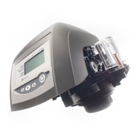
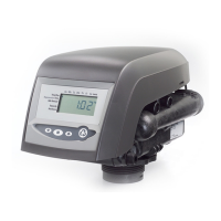
5) Check the included bypass assembly for the two
rubber gaskets and snugly tighten the assembly
to the back of the Autotrol 268/760 valve as
shown in Figure 8-C
6) Locate the two plumbing adaptors supplied
with your system. Insert the plumbing adapter
through the universal nut and then push down
the gasket over the adaptor flange as shown in
Figure 8-D below
 Loading...