Refer to
Selective Unlocking
Options on Pg4
& See note 1.5
See Note 7.0
& Table 1 (7.4)
SELECTIVE UNLOCKING
THESE OUTPUTS BELOW ARE NEGATIVE SWITCHING (MAXIMUM CURRENT 300mA)
To ground or +12V
as required
Not connected
+12V
Common
Coil
Coil
N.Closed
N.Open
TO TRUNK RELEASE SOLENOID
(PFK SOLENOID PART NO. 088-510)
TRUNK RELEASE
RELAY
30 85 86 87a 87
NOT SUPPLIED - G.P. RELAY
Part No. 436-900
INTERIOR LIGHT
See Note 10.0
and Table1 (8.3)
Drives interior light
See Note 10.0 & Table1 (8.3)
DRIVER'S
DOOR
SWITCH
DOORS
+ 12 V
Common
Coil
Coil
N.Closed
N.Open
+12V
+12V
Connect to
“BLUE" Door wire
RELAY REQUIRED FOR POSITIVE
INTERIOR LIGHT.
WITH POSITIVE DOOR SWITCHING
INTERIOR LIGHT WILL NOT FADE
ON AND OFF
INTERIOR
LIGHT
See Note 10.0
Not
connected
RELAY
30 85 86 87a 87
+ 12 V
G.P. RELAY Part No. 436-900
(NOT SUPPLIED)
PIN 21
PIN 1
PIN 8
PIN 5
PIN
16
TRUNK RELEASE
POSITIVE PULSE
BLACK/YELLOW WIRE
TRUNK RELEASE
BOOT
DOORS
POS DOORS
NEG
OUT
SPEAKER
OUTPUT
RED
BLACK
NEG BONNET
BATTERY BACK UP SIREN
BONNET
BLACK
SIREN
+ 12 V
See Note
9.0
PAGE
1 OF 5
DPFK 695/522
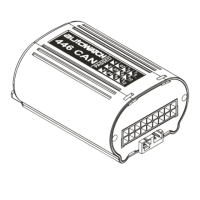
REAR VIEW OF
24-WAY HARNESS
1.
2.
3.
4.
5.
6.
7.
8.
9.
10.
11.
12.
13.
14.
15.
16.
17.
18.
19.
20.
21.
22.
23.
24.
Negative Doors + Dome Light driving
Can High
Can Low
Aux 2 (Windows/Pager) (White/Black wire)
Aux 3 (Trunk release) (Black/Yellow wire)
Not Used
Neg. Bonnet
Positive Doors
Service
Ground
+ 12V
Speaker / Siren / Horn
Unlock - Common (Blue wire)
Unlock - N/O (Grey wire)
Unlock - N/C (Yellow wire)
Aux 1 (Selective Unlock / Neg. Out when armed)
Ignition
Indicators
Indicator +12V
Indicators
Negative Boot
Lock - Common (Green wire)
Lock - N/O (Brown wire)
Lock - N/C (Violet wire)
ANTENNA
Do not sleeve or tape
antenna with other wires.
Run antenna separately
and try to position
away from metallic
objects
CAN programming connection.
Refer to programming
instructions.
CHASSIS
CHASSIS
+ 12 VOLTS
+ 12 VOLTS
GROUND
WIRE HARNESS INTO THE VEHICLE PRIOR
TO PLUGGING CONTROL MODULE IN
LED
CAN STATUS
PIN 2
PIN 3
PIN 10
PIN 11
PIN 7
PIN 12
PIN 19
PIN 13
PIN 22
PIN 9
PIN 18
PIN 20
PIN 4
PIN 15
PIN 24
PIN 14
PIN 23
PIN 17
CAN HIGH
CAN LOW
}
}
SLEEVED WITH
WIRES FROM
PIN 22, 23 & 24
SLEEVED WITH
WIRES FROM
PIN 13, 14 & 15
FUSE
+12V
NOTE : FUSES ARE
NOT SUPPLIED
+12V WHEN THE IGNITION IS
IN THE ON AND CRANK POSITION.
IGNITION (FUSED)
INDICATOR
+ 12 VOLTS
IGNITION
BOOT
+12V
Ignition
switch
GROMMET
INTERNAL RELAY CONFIGURATION
+12V
UNLOCK RELAY
LOCK RELAY
N.O. - GREY
N.O. - BROWN
N.C. - YELLOW
N.C. - VIOLET
COMMON - BLUE
COMMON - GREEN
SLEEVED
Hazard Pulse
See Note 11.0
& Table 1 (8,9)
JOIN TO THE
POSITIVE WIRE
OF INDICATOR
LIGHTS
+ +
LEFT
RIGHT
INDICATORS
INDICATORS
(UNDER CARPET SWITCH) USED FOR VALET MODE
AND ADDITIONAL FEATURES (SEE 4.0, 13.0 & 14.0)
BLACK
BLACK/GREY
SERVICE
REAR VIEW OF UNIT
Can be connected to Pager Module/Tracking System.
To select this function see note 4.0 & Table 1 (5.1)
Requires additional Window Closer Module
(PFK Part No. 210-000)
To select this function see 4.0
& Table 1. (5.1, 5.2, 5.3 & 5.4)
THE OUTPUT BELOW IS NEGATIVE
SWITCHING (MAXIMUM CURRENT 300mA)
OR
OR
OR
WINDOWS
PAGER/TRACKING
OR
OR
WHITE/
BLACK
WHITE/
BLACK
Wiring information will be supplied with the Module
}
}
}
REFER TO “VEHICLE SPECIFIC INFORMATION” FOR REQUIRED WIRING
MANDATORY WIRING
To other side
of circuit to be
immobilised
Not Connected
To one side of circuit
to be immobilised
Connect to neg out
when armed.
GP RELAY
PFK PART NO.436 900
87
87a
86
85
30
To ignition
NEG OUT WHEN ARMED
To select & adjust this Function
see Note 4.0 & Table 1
(4.1, 4.2, 4.3 & 4.4)".
To select this function
see Note 4.0 & Table 1 (4,4)
AUTOWATCH 446 RLC ALARM WIRING DIAGRAM
REV. 2
01/04/09