Technical Documentation: Fire Detectors used in hazardous areas
P-DET/EX/RCE/PM5/GKa/110995 12 Autronica Fire and Security AS
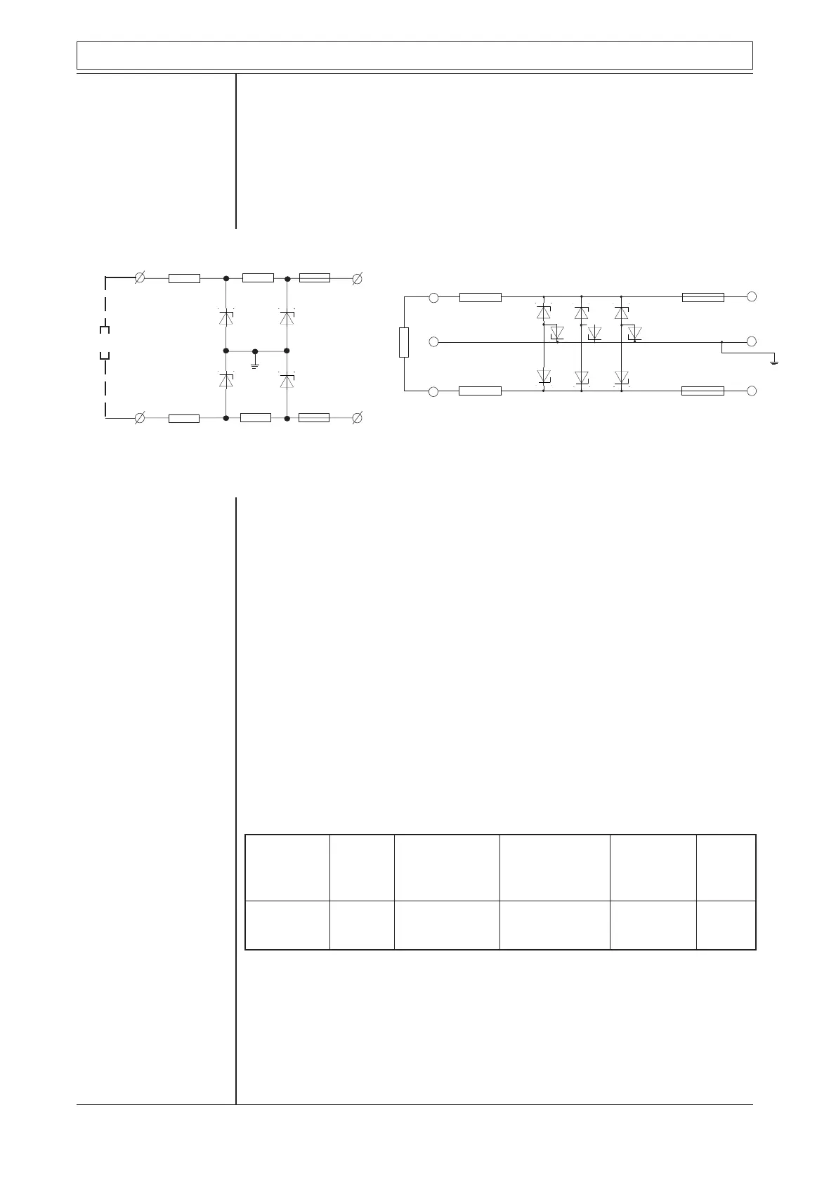
In this description the part regarding installation will be confined to our zener
barrier unit type BZ-32, mainly. This unit is built up by means of AC-zener
barrier as main component. The advantage of using this ac-barrier is explained
by the two sketches, and the associated description below:
R1
R2
Z1
Z2
Z3
Z4
R3
R4
Positive
barrier
Negative
barrier
F1
F2
PE
R
S
13
4
23
11
2
21
Resistor
R1
Resistor
R2
Fuse
F1
Fuse
F2
ZD1
ZD2
ZD3
ZD7
ZD8 ZD9
ZD4
ZD5
ZD6
Zener diodes
Zener diodes
Fig. 1 Fig. 2
Diagram fig.1 shows the connection of two zener barriers, one positive and one
negative, confining one zener barrier unit. This unit has been used for our fire
alarm detector lines (loops).
With no fault the arrangement is perfect, without any trouble. The PE- terminal
will then, electrically viewed, be situated midway between minus (-) and plus
(+), at the same potential as the earth terminal in the panel, approximately. The
PE-terminal and the panel's earth terminal must be connected together (outside
the hazardous area), and therefore an earth indication will be given by the
panel, if the PE-terminal is connected to minus (or plus). When the detector line
is disconnected by shorting the plus- and minus-wires (as in the BS-systems)
trouble will be introduced because then the zener barrier Z1 and Z2 will
connect the PE-terminal to minus.
Considering the same situation with ac-barriers (see fig. 2), it is easily shown
that the zener diodes ZD7, ZD8 and ZD9 will prevent the PE-terminal from
being connected to minus.
Data for zener barrier type Z667/Ex
Nominal Type Max. end to end Working voltage Max. voltage Fuse
Charact- no. resistance at 10mA leakage rating
eristics mA
18V 120W Z667/Ex 135.4W 14.5V 16.5V 50
18V 120W 135.4W 14.5V 16.5V 50
Zener barrier type Z667/Ex
R
S
PE
 Loading...