Technical Documentation: Fire Detectors used in hazardous areas
P-DET/EX/RCE/PM5/GKa/110995 15 Autronica Fire and Security AS
1.9 INSTALLATION DATA
Limitations w.r.t. capacitance in cable and detectors/call-points connected to zener
barrier type Z667/Ex (part of zener barrier units BZ-20/S and BZ-32).
For an intrinsically safe circuit connected to a zener barrier, there is a limitation as to how large a capacitance
(C
max
) the circuit can hold. C
max
will vary depending on which gas group is present in the area where there is a
danger from explosion.
For zener barrier Z667/Ex, the values are:
for gas group IIC : C
max
= 0.440 µF
for gas group IIB : C
max
= 1.32 µF
for gas group IIA : C
max
= 3.52 µF
The following parameters apply:
The total capacitance in the cable and detectors/call-points shall not exceed C
max
.
Max. number of units connected to each zenerbarrier in BZ-20 and BZ-32 is 10. The total capacitance in
each branch must not exceed C
max
.
Cable: Capacitance in cable varies with type, but if the value is unknown, use a value of 200 pF per
metre as maximum.
Detectors: Equivalent capacitance (C
i
/C
eq
) is for different detectors/call-points, as set during testing/certifica-
tion by NEMKO.
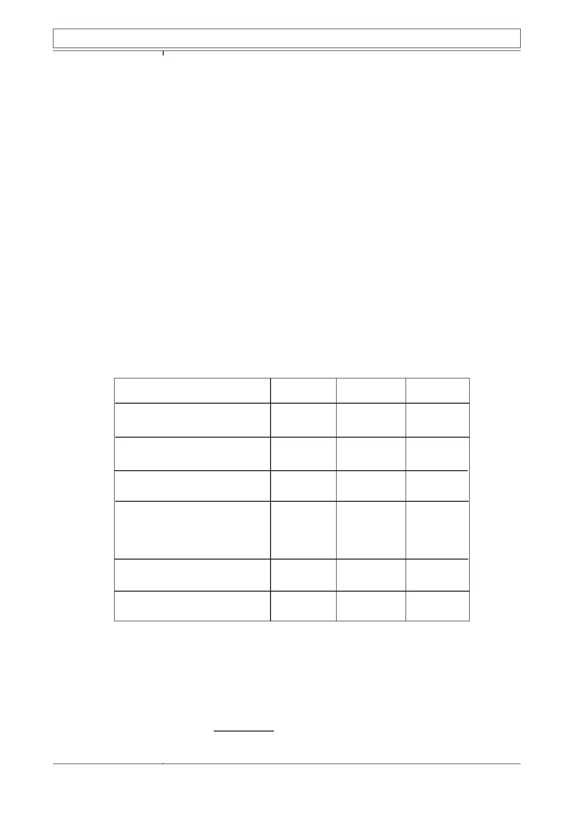
Group IIA Group IIB Group IIC
BD-26/Ex: C
i
= 36 nF
BD-27/Ex: C
i
= 36 nF 10 10 10
BE-30/Ex: C
i
= 80 nF 10 10 5
BE-34/Ex: C
i
= 80 nF
BH-31A/Ex: C
i
= 30 nF 10 10 10
BH-31A/S/Ex: C
i
= 30 nF
BJ-20B/Ex: C
eq
≤ 0,2 µF10 6 2
BJ-31/Ex: C
eq
≤ 0,2 µF
BF-35/Ex: C
eq
≤ 10 nF
BF-32M/Ex C
eq
≤ 10 nF 10 10 10
BF-52/Ex: C
eq
≤ 10 nF
BF-53/Ex: C
eq
≤ 10 nF
BF-33/Ex: C
eq
≤ 0,4 µF 8 3 1
BF-34/Ex: C
eq
≤ 0,4 µF
BN-35/Ex: C
eq
≤ 10 nF 10 10 10
BN-32M/Ex: C
eq
≤ 10 nF
The number of detectors / call-points is calculated with a cable of 200 m (200 m x 200 pF).
Notes: 1 µF = 1.000 nF = 1.000.000 pF
E.g. for gas group IIC (C
max
= 0.440 µF) for a single zener barrier type Z667/Ex.
50 m cable (à 200 pF) = 10 nF
2 x BF-35/Ex (à 10 nF) = 20 nF
7 x BH-31A/Ex (à 30 nF) = 210 nF
1 x BJ-31/Ex (à 0.2 µF) = 200 nF
440 nF = 0.440 µF
 Loading...