19
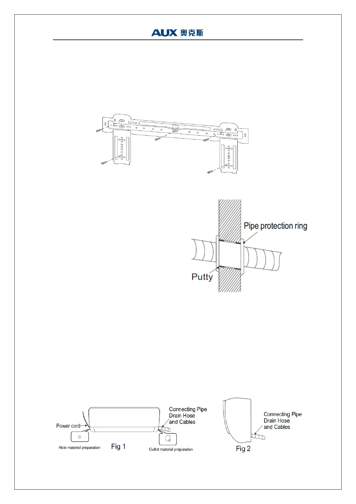
11 Mounting plate
1. The wall for installation of the indoor unit shall be hard and firm, so as to prevent
vibration.
2. Use the "+" type screw to fasten the peg board, horizontally mount the peg board
on the wall, and ensure the lateral horizontal and longitudinal vertical.
3. Pull the peg board by hand after the installation, to confirm whether it is solid.
12 Wall-through Hole
1. Make a hole with an electric hammer or a
water drill at the predetermined position on
the wall for piping, which shall slant
outwardly by 5°-10°.
2. To protect the piping and the cables from
being damaged running through the wall,
and from the rodents that may inhabit in
the hollow wall, a pipe protecting ring shall
be installed and sealed with putty.
Note: Usually, the wall hole is Φ60mm~
Φ80mm. Avoid pre-buried power wire
and hard wall when making the hole.
13 Route of Pipeline
1. Depending on the position of the unit, the piping may be routed sideway from the
left or the right ( Fig 1 ), or vertically from the back( Fig 2 )(depending on the pipe
length of the indoor unit). In the case of sideway routing, cut off the outlet cutting
stock of the opposite side.
2. The power cord may be routed separately from the piping. Cut off the outlet cutting
stock and then run the power cord through the hole, keeping the remaining part as
a protection from rodents.
 Loading...