User Manual
www.AvantcoEquipment.com 11
76
WORM GEAR SHAFT ASSEMBLY
FIGURE 4
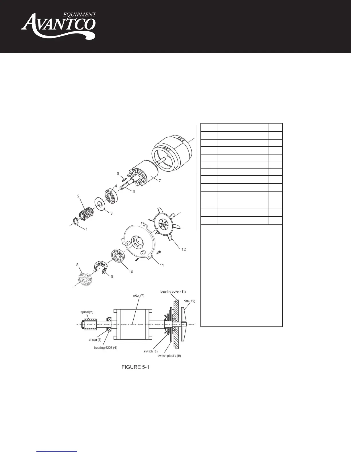
MOTOR UNIT
FIGURE 5
ITEM DESCRIPTION QTY
1 Stop Ring 1
2 Worm Gear 1
3 Oil Seal 1
4 Bearing 6203 1
5 Key 4*22 1
6 Axle 1
7 Rotor 1
8 Governor 1
9 Governor Plate 1
10 Bearing 6203 1
11 Bearing Cover 1
12 Fan 1
NOTES:
• If the motor does not work, first verify
the power source and connection. Next,
check for damaged or faulty wiring or
connections inside the mixer. A faulty
motor may be the result of incorrect
voltage, broken wires, a defective cen-
trifugal governor. Motor damage may
also be cause by bowl over load d
uring
mixing.
• Motor set includes motor axle (6),
rotor (7) and stator.
• Figure 5-1 is component system
diagrams of motor.
ITEM DESCRIPTION QTY
1 Bearing 6201 1
2 Gear Axle 1
3 Key 5*14 1
4 Gear 1
5 Stop Ring 1
6 Bearing 6201 4
NOTES:
• C-Type stop ring (5) has to be fixed
when reassembling.