EasyManua.ls Logo

Avantgarde SOLO - Page 8

Avantgarde SOLO
18 pages
Print Icon
To Next Page IconTo Next Page
To Previous Page IconTo Previous Page
Loading...
www.avantgarde-acoustic.de page 8
Version 1.4 – May 25, 2007
SOLO
OPERATING INSTRUCTIONS
STBY
01
02
03
04
05 (AV)
100
80
60
40
20
0
LOW FEEDBACK CASCODE POWER STAGE
12V DC REMOTE
SPKR OUTPUT
RIGHT SPEAKER
INPUT
UNBALANCED
5 (AV)
4
3
R
L
INPUT
BALANCED
RIGHT
LEFT RIGHT
LEFT
PRE OUTPUT
BALANCED
RIGHT
LEFT
12V DC REMOTE
SPKR OUTPUT
LEFT SPEAKER
MODEL.THREE MANUFACTURED IN GERMANY BY AVANTGARDE ACOUSTIC
DO NOT OPEN.
RISK OF ELECTRICAL SHOCK
CAUTION!
2
1
PIN1 GND
PIN2
PIN3
POWER
1 0
SERIAL no.
100V/
5,0A
115V/
5,0A
230V/
3,15A
slow fuses only!
REM
GND
HIGH EQ
LOW EQ
HIGHPASS
VOLUME
INPUT
OFF
20
120
ON
OFF
ON
0 +3 −2
4
5
2
3
XLR
XLR
RCA
XLR
6
4
REM
GND
HIGH EQ
LOW EQ
HIGHPASS
VOLUME
INPUT
OFF
20
120
ON
OFF
ON
0 +3 −2
STBY
01
02
03
04
05 (AV)
100
80
60
40
20
0
LOW FEEDBACK CASCODE POWER STAGE
12V DC REMOTE
SPKR OUTPUT
RIGHT SPEAKER
INPUT
UNBALANCED
5 (AV)
4
3
R
L
INPUT
BALANCED
RIGHT
LEFT RIGHT
LEFT
PRE OUTPUT
UNBALANCED
RIGHT
LEFT
12V DC REMOTE
SPKR OUTPUT
LEFT SPEAKER
MODEL.THREE MANUFACTURED IN GERMANY BY AVANTGARDE ACOUSTIC
DO NOT OPEN.
RISK OF ELECTRICAL SHOCK
CAUTION!
2
1
PIN1 GND
PIN2
PIN3
POWER
1 0
SERIAL no.
100V/
5,0A
115V/
5,0A
230V/
3,15A
slow fuses only!
4
5
2
3
XLR
XLR
RCA
6
6
RCA
GRAPHIC 6
GRAPHIC 5
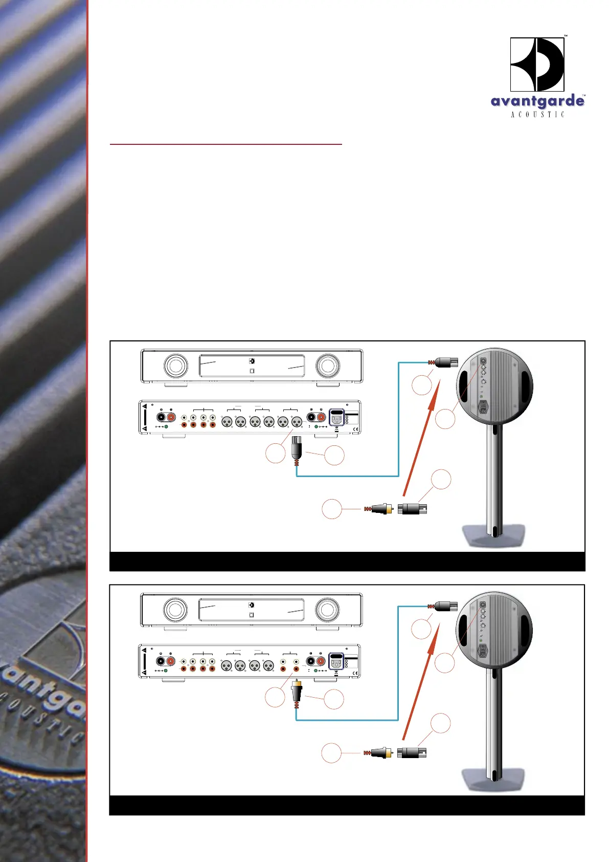
CONNECTION TO PREAMPLIFIERS
(See graphic 5 and 6)
The SOLO can as well be directly driven by
LINE LEVEL signals preamplifiers, surround
processors, mixing consoles etc. (via RCA
󱂬 or
XLR connectors).
The SOLO power module has one female XLR-
INPUT 󱂨 to directly connect balanced preamplifier
signals via the respective XLR connector.
Additional the system is shipped with an XLR-to-
RCA adapter
󱂫. This way unbalanced sources
can be easily connected.
1. Connect the PRE OUT (or REAR OUT, CENTER
OUT) OUTPUT terminals of your preamplifier
󱂩 with the SOLO INPUT terminal 󱂨. The XLR
plug 󱂪 should be configured:
PIN 1 = GROUND
PIN 2 = SIGNAL (in phase)
PIN 3 = NOT used
2. Only now, connect the AC power cords of the
components to a household AC outlet and
turn on the speaker.
Tips and tricks to determine the optimal
position of the speakers can be found in the
respective chapter in this manual.

Related product manuals