- 16 -
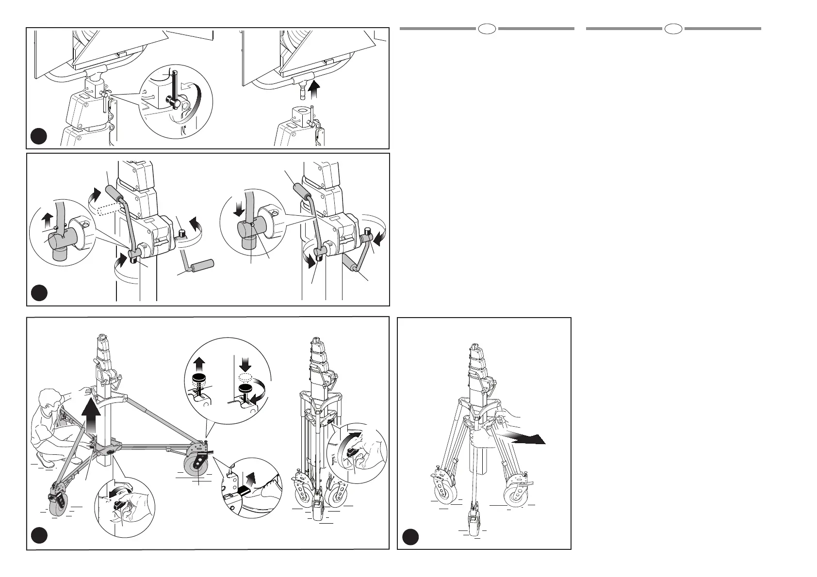
Remove load from the stand by opening the
locking screw “G” (fig. 16)
Rotate the handles “X” into transportation/storage
position (fig. 17) by:
- unlocking set screw “I” anticlockwise
- raise the levers “X” in order to unhook the pin
“M” from the channel of the handle axle “R1”
- rotate handle “H” into transportation/storage
position
- lock handle “H” in position by tightening set
screw “I” clockwise so pin “M” is secured into
the channel of the handle axle “R2”.
Release the wheel locks “P” (fig. 18) if wheels are
fitted.
Release the wheel direction locking position “Y”
by pulling out pin “U” and rotate it 90°.
Unlock knob “E” and push the bottom centre
column casting up “L” (using handle) and then
lock the knob as shown in figure.
With stand in closed position, it is possible to
move it: it is recommended to open a little bit the
base in order to have more stability during
transportation (fig. 19).
Rimuovere il carico dallo stativo allentando la vite
di bloccaggio “G” (fig. 16)
Ruotare le manovelle “X” in posizione trasporto/
riposo (fig. 17) come segue:
- sbloccare la vite di bloccaggio “I” in senso
antiorario
- sollevare le leve “X” per sganciare il perno “M”
dalla sede sull’asse della manovella “R1”
- ruotare la manovella “H” in posizione
trasporto/riposo
- bloccare la manovella “H” in posizione
serrando la vite di bloccaggio “I” in senso
orario in modo che il perno “M” sia inserito
nell’apposita sede sull’asse della manovella
“R2”.
Sbloccare i freni delle ruote “P” (fig. 18) se
necessario.
Liberare il bloccaggio della direzione delle ruote
“Y” sollevando il perno “U” e ruotandolo di 90°.
Sbloccare la manopola “E” e sollevare la crociera
inferiore “L” della colonna centrale (tramite
l’apposita maniglia), quindi bloccare la manopola
come mostrato in figura.
Con lo stativo in posizione chiusa è consentito lo
spostamento: si raccomanda di aprire
parzialmente la base per avere maggiore stabilità
durante il trasporto (fig. 19).
17
18
X
X
X
X
M
R2
I
I
I
M
R1
I
5
5
2
3
4
1
1
16
G
2
Y
P
E
L
U
1
1
2
4
3
5
6
7
19
GB I
E