Do you have a question about the Avenger B7057 LONG JOHN SILVER and is the answer not in the manual?
Specifies the maximum weight the stand can support (120 kg / 265 lb).
Defines the operational temperature limits for the product.
States that only experienced personnel should operate this product.
Emphasizes the need for a stable ground surface to support the stand and its load.
Ensures the central column is perfectly level before raising any attached equipment.
Confirms that attached instruments must be correctly locked and stable.
Advises to balance loads, especially when using T bars.
Recommends anchor wires/braces for outdoor use exceeding 2.5m height.
Recommends periodic checks of the stand's condition.
Warns against leaving the product unattended in public areas.
Advises checking the pressure of the pneumatic wheels.
Emphasizes reading instructions carefully before use.
States the maximum load capacity is 120kg.
Specifies the operating temperature range as -20° to +60°.
Only experienced personnel are authorized to use this product.
Ensures the ground is stable and can support the stand and its load.
Ensure the central column is perfectly level before raising equipment.
Ensure attached equipment is correctly locked and stable.
All loads must be balanced, especially with T-bars.
Recommends securing the stand with guy ropes for outdoor use over 2.5m.
Regularly check the stand's condition.
Do not leave the stand unattended in public areas where it could endanger the public.
Check the pneumatic tire pressure.
The stand has adjustable levelling legs to compensate for minor ground variations.
The stand must be set up on firm ground capable of bearing its weight and load.
Use a board "F" under wheels on soft ground to prevent sinking.
For heights over 2.5m outdoors, use anchor wires/braces (supplied).
Release the wheel locks "P" if wheels are fitted.
Release the wheel direction locking by pulling pin "U" and rotating 90°.
Unlock knob "E".
Push bottom centre column casting "L" to partially open the base.
Adjustable legs compensate for slight ground level differences.
Install on a firm surface capable of supporting the stand and load.
Place pads "F" under wheels on soft ground to prevent sinking.
For heights over 2.5m outdoors, secure with guy ropes/attachments.
Steps to open the base and level the stand.
Release wheel brakes "P".
Release wheel direction lock by pulling pin "U" and rotating 90°.
Loosen the locking knob "E" to adjust the base.
The stand is supplied with levelling legs for ground compensation.
Set up on firm ground to support weight and load without sinking wheels.
Place board "F" under wheels on soft ground.
Advised to use anchor wires/brace for outdoor use above 2.5m.
Place the product in the working area.
Unlock knob "E" and push down column casting to open base.
Lock wheels with "P" and direction with pin "U".
Wheel plate "Y" has 6 holes for setting wheel direction.
Three adjustable legs compensate for ground level differences.
The stand has telescopic legs for minor ground level compensation.
Set up on a firm surface supporting stand and load without sinking wheels.
Use pad "F" under wheels if ground is soft.
For heights over 2.5m outdoors, secure with guy ropes/attachments.
Lower the centre column casting to partially open the base.
Place the stand in the desired working area.
Unlock knob "E", push down column to fully open legs, tighten knob.
Lock wheels with "P" and set direction with pin "U".
Wheel plate has 6 holes for setting wheel direction.
Three adjustable legs compensate for ground level differences.
Unlock the set screw "I" anticlockwise.
Raise levers "X" to unhook pin "M" from handle axle "R".
Rotate handle "H" into the operating position.
Lock handle "H" by tightening set screw "I".
Ensure the stand is in the working position and levelled.
Warning not to tilt the stand when loading equipment.
Open locking screw "G" before inserting spotlight spigot.
Secure the spotlight spigot by locking screw "G".
Recommend safety brace cables for heights over 2.5m or windy conditions.
All loads should be balanced, especially with T bars.
Loosen the set screws "I" anticlockwise.
Pull levers "X" to unhook pins "M" from handle axle "R1".
Rotate handles "X" outwards to operating position.
Lock handles "X" by tightening set screws "I".
Ensure the platform is level in the working position.
Warning not to tilt the stand to attach equipment.
Release locking lever "G" before inserting lighting spigot.
Secure equipment by turning locking lever "G".
Recommend safety cables for heights over 2.5m or windy conditions.
Balance all loads, especially T-bar usage.
Ensure no obstructions when raising the stand to the desired height.
Check stand setup, leveling, load, and balance before adjusting height.
Raise the load by turning handles "H" clockwise.
Red button "N" is a secondary safety lock that vibrates during raising.
Checks for load excess, column damage, or obstructions if raising is difficult.
Warning not to move the stand when the load has been raised.
Ensure the stand can be adjusted freely to the desired height.
Check setup, load capacity, balance, and obstructions before extending.
Increase load by turning handles "H" clockwise.
Red button "N" is a safety lock that vibrates during extension.
Checks for load excess, damage, or obstructions if extension is difficult.
Do not move the stand after extending the columns.
Ensure no obstructions before lowering the stand.
Press red button and turn handle anticlockwise to lower columns.
Do not stand or climb on the base or castings.
Ensure no elements obstruct the column height reduction.
Press red button "N" and turn handle anticlockwise to reduce height.
Do not stand or step on the base or castings.
Release the wheel locks "P" if wheels are fitted.
Release the wheel direction locking by pulling pin "U" and rotating 90°.
Wheel direction lock allows locking one or two wheels for specific direction.
Release the wheel brakes "P".
Release the wheel direction lock by pulling pin "U" and rotating 90°.
Wheel direction lock allows setting direction by locking one or two wheels.
Unlock the set screw "I" anticlockwise.
Raise levers "X" to unhook pin "M" from handle axle "R1".
Rotate handle "H" into transport/storage position.
Lock handle "H" by tightening set screw "I".
Loosen set screw "I" anticlockwise.
Pull levers "X" to remove pins "M" from axle "R1".
Rotate handles "X" to transport/storage position.
Lock handles "X" by tightening set screws "I".
Check condition of chains raising/lowering columns via inspection holes "Q".
Recommends thorough cleaning after long periods of storage.
Check safety lever "N" operability by cranking up and pressing down.
De-ice iced columns/mechanism carefully, avoid direct flame or de-icing fluids.
Check condition of chains raising/lowering columns via inspection holes "Q".
Recommends inspecting the stand carefully after prolonged disuse.
Check safety lever "N" functionality by raising and pressing.
De-ice the mechanism carefully, avoiding direct flame or de-icing products.
| Payload | 30 kg |
|---|---|
| Leg Cross Section | Round |
| Color | Silver |
| Material | Steel |
| Top Attachment | 5/8'' (16mm) spigot |
| Leg Size | 25 mm |
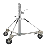
| Stand Type | Wind-Up Stand |
| Maximum Height | 370 cm |