Page 4
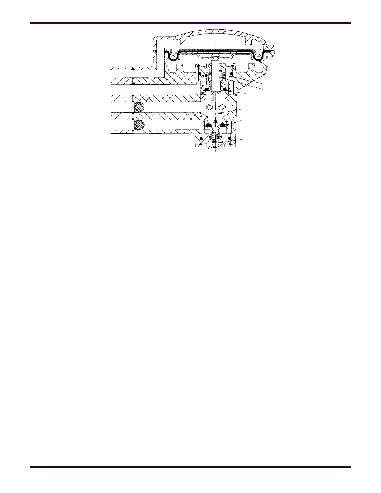
Referring to Figure 4, with supply air
pressure present in port 1 and no air pressure
present on the control diaphragm 36, both the
supply valve 7 and the exhaust valve 24 will be
seated by their respective springs. Assume that
air pressure is admitted to the control port 2 of
the valve. This pressure will be delivered to the
upper side of diaphragm 36 causing it to move
downward, carrying diaphragm stem 20 with it.
During this movement, the diaphragm stem will
contact the differential type supply valve 7 and
unseat it by compression of spring 5. Supply air
from port 1 will then flow past the unseated
valve to the delivery port 3 where it is piped to
the device being operated. Supply air also flows
through the choke in the exhaust valve cage 22
to the underside of the control diaphragm 36.
When the pressure under the diaphragm is
substantially equal to the control pressure on top
of the diaphragm, the diaphragm assembly will
move back toward its initial position and the
supply valve will seal, aided by spring 5, thus
cutting off further flow of supply air to the
delivery port.
The relay valve will maintain this delivery
pressure against leakage. In the case of a
reduction in delivery pressure, the higher
pressure on the upper side of the diaphragm will
cause movement downward repeating the
application cycle and restoring the delivery
pressure to the desired value.
When the control pressure to the valve is
reduced, the higher pressure on the
underside of the diaphragm 36 will cause it to
move upward carrying stem 20 with it. During
this movement, a shoulder on the diaphragm
stem will contact the differential type exhaust
valve 24 and unseat it by compression of
spring 27. Air from the delivery port will then
flow past the unseated exhaust valve to
atmosphere reducing the pressure in the
device being operated. When this pressure
has been reduced to balance the pressures
on diaphragm 36, the diaphragm assembly
will move back toward its initial position and
the exhaust valve will seal aided by spring 27,
thus cutting off the flow of air to exhaust. If the
control pressure is completely removed from
the diaphragm, the valve will completely
e x h a u s t t h e d e l i v e r y p r e s s u r e .
During an application of air to an
operating device, if the pressure in the
delivery line should increase due to
temperature variation or other causes, this
condition will unbalance the diaphragm to
repeat the exhaust cycle described above
until the desired pressure is again reached.
From the foregoing it will be seen that the
C-2 Relay Valve will reproduce in the delivery
line a pressure equal to that in the control line
and will maintain this pressure against
leakage or temperature effect.
Fig. 4. Diagrammatic View
22
36
27
24
20
7
5
CONTROL———-2
EXHAUST ———EX
DELIVERY ———3
SUPPLY ——–—-1