Do you have a question about the Avery Berkel CX20 SERIES and is the answer not in the manual?
General information about the manual's purpose and usage.
Records amendments made to the manual.
Lists and defines technical terms and acronyms used in the manual.
Critical safety precautions to prevent injury or damage during operation and servicing.
Guidelines and procedures to follow for safe and effective servicing.
Information regarding user handbooks and notation used in the publication.
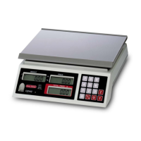
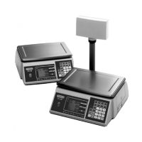
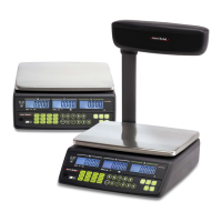
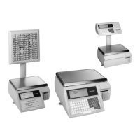
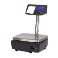
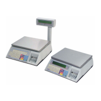
Overview of the different models within the CX20, CX30, and CX34 series of scales.
Provides a general overview of the CX20, CX30, and CX34 series scales and their features.
Details specifications such as power requirements, scale range, and dimensions for the scale models.
Describes the physical construction and components of the CX20/CX30, CX20 W/CX9/A702, and CX34 units.
Explains the electrical system, power flow, and data processing within the scales.
Details how the units can be networked as Master or Slave devices.
Outlines the diagnostic software and routines available for testing machine functions.
Introduces the procedures for disassembling and assembling the machines.
Step-by-step instructions for disassembling and servicing the CX20 and CX30 models.
Procedures for disassembling and servicing the CX20 W and CX9/A702 models.
Instructions for disassembling and servicing the CX34 model.
Details the installation procedure for the CX20 W and CX/A702 machines with wrapping systems.
Provides a step-by-step guide for installing the CX20 W and associated components.
Covers the EC approval certificates and definitions related to non-automatic weighing instruments.
Explains the purpose of setting up procedures performed in Service Mode.
Details how to enter and utilize the Service Mode for machine configuration and servicing.
Describes how to configure machine settings via the menu option.
Explains the procedure for calibrating the machine using the menu option.
Outlines how to clear and re-initialize the machine's memory.
Describes the RAM check procedure and how format memory works.
Details the procedure for checking machine calibration using a known weight.
Refers to Section 8 for detailed test procedures.
Explains how to change the Service Access Code (SAC) number.
Describes how to adjust the printing density on the thermal paper.
Explains how to create and manage label formats, available on LS machines.
Explains the purpose of machine configuration for customer requirements and network systems.
Details the process of configuring the machine, including system configuration and country override.
Step-by-step guide on how to input configuration codes for the machine and system.
Provides tables listing various configuration options for machine settings.
Explains that calibration data is stored in EEPROM and covers span, zero, and linearity settings.
Details how to adjust asymmetric overload stops on CX20 and CX30 models.
States that central overload stops are factory set and require no adjustment.
Notes that overload stops on the CX34 are factory set and require no adjustment.
Provides a step-by-step procedure for calibrating the unit using service mode.
Explains the unit's self-test at power-up and available diagnostic testing.
Describes how to set or change the date and time on the machine.
Details various tests available within the SCALE TEST menu for checking scale functions.
Explains how to simulate normal operations to check communication and performance.
Introduces the LABEL FORMATS menu for creating and editing label formats according to customer requirements.
Covers the types of label formats available, including pre-programmed and flexible options.
Outlines the three stages for creating a new label format: design, co-ordinates, and programming.
Explains how to program new label formats or edit existing ones.
Describes how to clear pre-programmed field data in label formats, setting them to default.
Allows copying an existing label format to a new format number.
Prints the selected label format showing boxes for fields and their codes.
Lists and explains error messages displayed on the commodity display and their meanings.
Describes how error numbers appear on the TEST REPORT indicating software or system failures.
Details the functions of the main PCB, including circuitry for operation and peripheral connections.
Provides instructions for removing and fitting the main PCB for CX20/CX30, CX20 W, and CX34 models.
Describes the two displays used on the CX20 unit and their characteristics.
Explains how displays are check-scanned during boot-up to verify segment and driver functionality.
Provides procedures for removing and fitting integral and tower-mounted display PCBs.
Describes the displays used on CX30/CX34 machines, including their mounting and components.
Explains how displays are check-scanned during power-up to verify segments and drivers.
Mentions switch settings and LED allocation for display PCBs, with a caution against adjusting powered up.
Provides procedures for removing and fitting display PCBs and assemblies for CX30 and CX34 models.
Details the tactile keyboard types and their connection to the main PCB.
Explains that the keyboard is check-scanned during power-up.
Provides procedures for removing and fitting keyboards for CX20/CX30 and CX34 models.
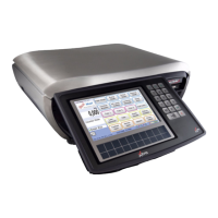
Describes the CX30 TK machine as a customer self-service, label-only unit with large keyboards.
Details the mechanical components of the CX30 TK keyboard assembly and controller.
Explains the electrical setup of the keyboard controller PCB and its interface.
Details the functions and specifications of the keyboard controller PCB.
Provides step-by-step instructions for servicing the keyboard assembly and controller PCB.
Explains the function of the power supply unit in transforming and smoothing mains electricity to lower-voltage outputs.
Details procedures for accessing and servicing the power supply unit, including fuse replacement.
Step-by-step guide to access the power supply unit for testing or replacement in CX20/CX30 models.
Step-by-step guide to access the power supply unit for testing or replacement in CX34 models.
Instructions on how to safely isolate and replace a fuse in the power supply unit.
Describes the transducer assembly for CX20/CX30 and CX34 models, including its components and function.
States that the transducer must be tested as part of the unit, not as a separate part.
Explains the role of the A/D PCB in converting analogue signals from the transducer to digital form.
Provides procedures for removing and fitting the transducer for CX20/CX30 and CX34 models.
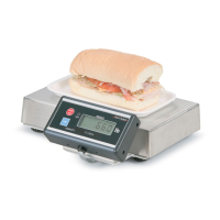
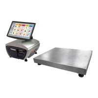
Describes the CX9/A702 platform's use with ULMA wrapping machines and its components.
Lists the operating and storage specifications for the CX9/A702 platform.
Details procedures for removing and fitting the transducer and cross assembly using special tools.
Describes the complete printer unit, its components, and how it prints receipts.
Explains how to test the printer and adjust stepper motor current.
Provides procedures for removing, fitting, cleaning, and changing parts of the printer.
Describes the versatile printer capable of printing thermal tickets and self-adhesive labels.
Explains printer scanning at power-up and stepper motor current adjustment.
Details procedures for removing, fitting, cleaning, and changing components of the label and receipt printer.
Explains how CX20/CX30/CX34 machines can be networked as Master or Slave units.
Provides details on network conductor cabling types and colour coding.
Describes the optional communications controller PCB and its role in system communication and data storage.
Details network connections for Master and Slave units when using a communications controller.
Identifies the main components on the Comms PCB, including integrated circuits, links, and connectors.
Refers to external documentation for servicing the C918 external comms controller unit.
Describes the RS232 interface PCB's function for communication with wrapping machines and printers.
Explains the RS232 interface circuit, including DCU channel multiplexing and wrapper control signals.
Provides instructions for replacing the RS232 interface PCB on the CX20 W.
Shows connector pin details on the main PCB for CX20/CX30 models.
Illustrates PCB interconnection diagrams for the CX20 W model.
Provides configuration option tables for software prior to Phase 1.3 release.
Explains label formatting, including calculating offsets and field data.
Exploded view and parts list for the CX20 series components.
Exploded view and parts list for the CX20 W model components.
Exploded view and parts list for the CX30 series components.
Exploded view and parts list for the CX30 TK head-up display assembly.
Exploded view and parts list for the CX30 TK column and keyboard support.
Exploded view and parts list for the CX30 TK keyboard assembly.
Exploded view and parts list for the CX9/A702 remote weighing platform.
Introduces the addendum covering Phase 1.4 upgrade and CX34 parts list.
Details new print head resolutions and density settings for Rohm and Axiohm printers.
Provides configuration option tables for machines with Phase 1.3 software and earlier.
Mentions new label fields and fonts available with the new high-resolution printers.
Refers to Section 10 for error messages, highlighting new ones like AUDIT 90% FULL.
Refers to Sections 11 and 24 for main PCB details and wiring, noting addition of PL22.
Lists part numbers for the Main PCB and specific printers.
Provides a parts list for the main assembly and components of the CX34 hanging scale.
Introduces the addendum covering Phase 1.5 software upgrade and new main PCB details.
Presents configuration option tables reflecting Phase 1.5 software.
Notes that test reports now show both comms controllers.
Discusses printing nutritional labels with wrappers and potential issues.
Mentions changes to continuous paper mode and the "REMOVE WEIGHT" display for ADF printers.
Explains printer selection logic and increased communications timeout for high-resolution printers.
Describes changes to the LAST PACK signal transmission affecting ULMA wrappers.
Specifies the correct jumper setting for Link LK7 on the Comms PCB.
Details the new main PCB part number and its compatibility.
Notes the requirement to enable the barcode scanner option and create formats.
Covers enabling euro price printing, assigning euro keys, and euro conversion procedures.
Provides tables listing firmware numbers for main cores and by country.
| Model | CX20 SERIES |
|---|---|
| Display | LCD |
| Interface | RS-232 |
| Protection Rating | IP65 |
| Readability | 5g (15kg) |
| Power Supply | AC adapter |
| Material | Stainless steel |