PRINTER SYSTEMS ASIA
PRINTER SYSTEMS ASIA
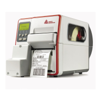
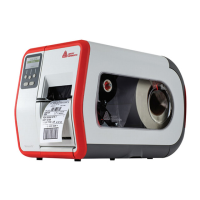
Cutter 2000
Cutter 2000
Installation layout in the AP 5.4 basic
A Data bus (14-core)
B 5V, 45V supply voltage (pink, black (3 x), blue (2 x))
C BLDC output stage board
D Sensor (white, blue, black)
E Do not connect the stepper motor (blue, gray, yellow, green)!
F BLDC motor (6-core)
G 5V supply voltage (red, black)
G 5V supply voltage (red, black)
(메인보드 우측하단에 위치함)
52
 Loading...