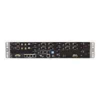
5-4 Aviat Networks
Chapter 5. Installing the IRU 600
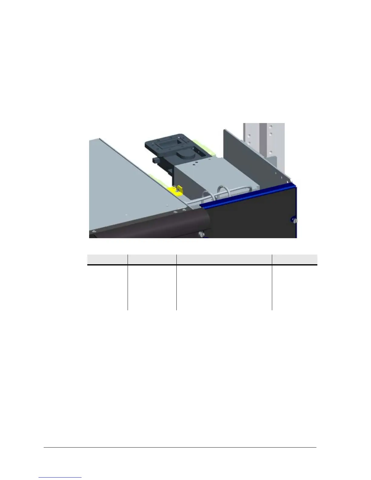
Connect Waveguide(s) to Antenna Ports(s)
Connect the ACU antenna port(s) to the main waveguide(s) using appropriate lengths
of flexible waveguide.
For information on required waveguide flanges, and recommended waveguide type,
refer to Table 5-1.
Remove and discard any protective flange/port covers before installation.
Figure 5-3. ACU and Waveguide Connection
Table 5-1. Waveguide Flange Type
Power Supply
Standard power RFUs are powered over the IF cable from its INU/INUe.
High power RFUs are additionally powered using a separate DC input on the RFU
front panel.
• The high power RFU provides a wide-mouth connection for +/- 21 to 60 Vdc. Both
+ve and -ve pins are isolated from chassis ground.
• The power connector (D-Sub M/F 2W2) and cable is identical to that used for the
INU. See Power Cables.
• Run the supplied power cable through to the power pick up point, which should
be protected by a circuit breaker or fuse in the rack. The circuit breaker or fuse
should have maximum capacity of 8 A.
• For a -48 Vdc supply, connect the blue wire to -48 Vdc (live), and the black wire
to ground/+ve.
Freq, GHz Flange Type Holes Waveguide
6 • CPR 137 G • All open for # 6-32 screws • WR 137
7 • CPR 112 G • 8 x #10-32 tapped holes • WR 112
8 • CPR 112 G • 8 x #10-32 tapped holes • WR 112
10, 11 • CPR 90 G • 8 x #8-32 tapped holes • WR 90