5
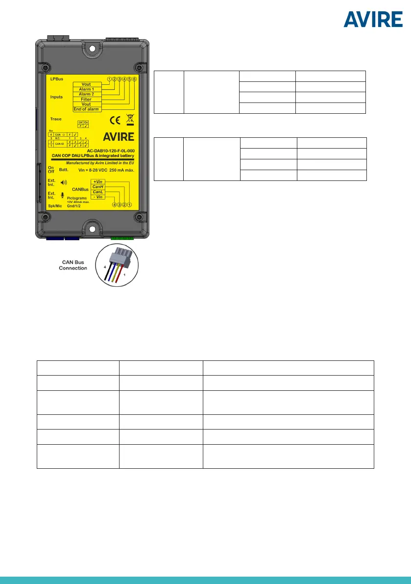
J8 CAN BUS
4 - Vin
3 CAN L
2 CAN H
1 +Vin
J9
CANBus connection on DCP
CANBus connection on DAU
J9 CAN BUS
1 +Vin (8-28 VDC)
2 CAN H
3 CAN L
4 -Vin (Ground)
LED INDICATORS / PICTOGRAMS
External LED indicators can be connected to the DAU through the J10 connector, as can be seen in
the wiring diagram on page 2.
The following table describes the operation of the two LEDs (green and yellow) on the DAU:
Yellow LED Green LED FUNCTION
OFF OFF End of alarm or Device on standby
ON OFF Alarm started, communication is established
OR End of voice communication
ON ON Start voice communication
OFF ON Audio module communication established
OFF Quick Flashing External audio module communication
established
 Loading...