Page 5
1. Place the protective display cover in the display cut-out in the elevator panel.
NOTE: The display cover has protective plastic on the front and back that should be removed before installation.
2. Mount the elevator unit over the display cover in the elevator panel and secure using appropriate mounting
hardware.
3. If not already mounted, mount the external USB camera in the desired location.
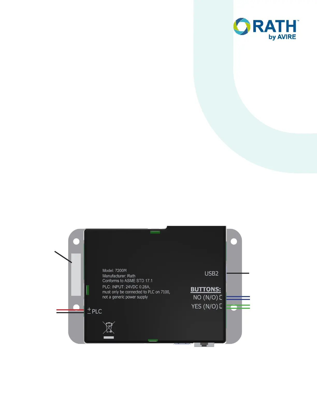
4. Wire either “YES” or “DOOR OPEN” button to the “YES” button screws on the 8-pin green terminal connector.
5. Wire either “NO” or “DOOR CLOSED” button to the “NO” button screws on the 8-pin green terminal connector.
6. Plug the 8-pin terminal connector into the “BUTTONS” port on elevator unit.
7. Plug USB Cable from external USB Camera into “USB2” port on elevator unit.
8. Strip back and expose 1/4” of wire on individual conductors of the 18AWG wire pair ran from machine room unit.
9. Connect the single pair of wires ran from the “PLC” connector on the machine room unit to the green two-pin
terminal connector verifying the positive and negative on the elevator unit matches the machine room unit.
Plug the terminal connector into the “PLC” connector the elevator unit.
Maximum distance limitation from Machine Room unit to Elevator unit is 1000 ft.
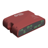
Elevator Unit
ID # # # # # #
No or Door
Closed Button
Yes or Door
Open Button
Two-Wire
Connection
to Machine
Room Unit
External USB
Camera
+
-
SmartView ID
Number
 Loading...