- 14 -
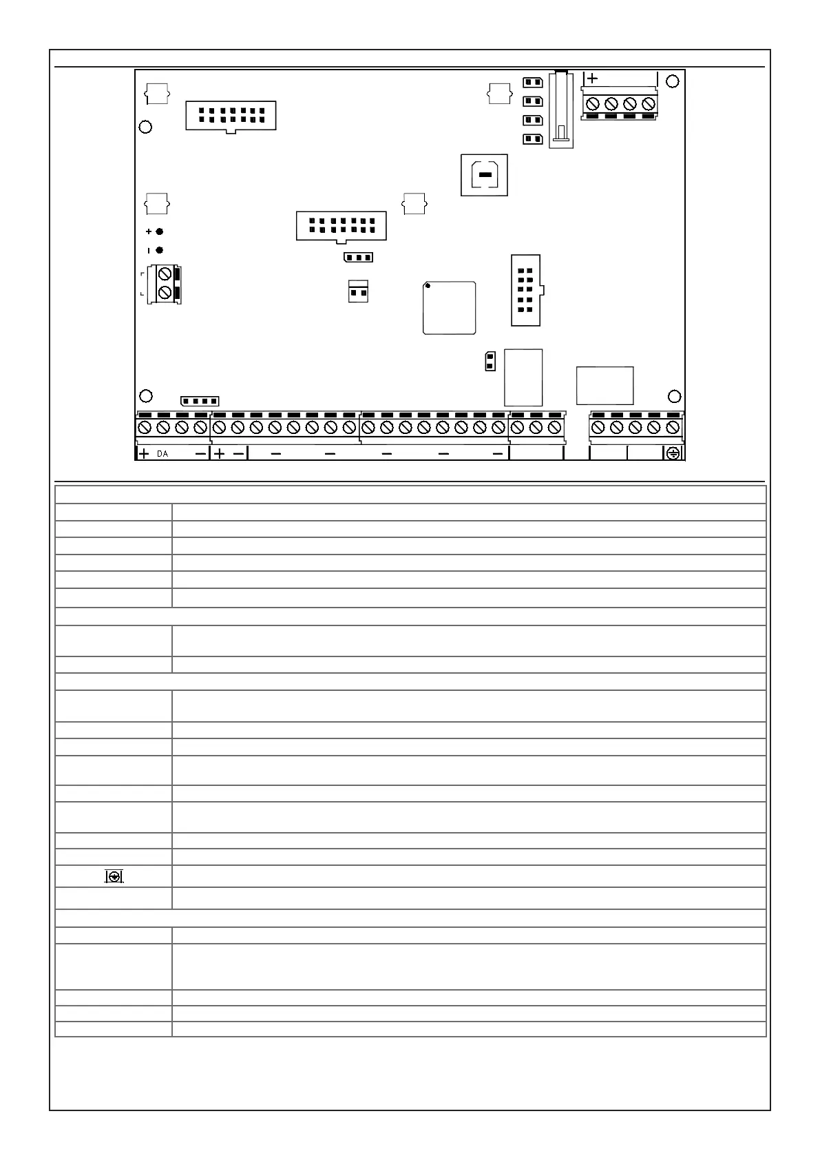
Control panel board CAPTURE 32, CAPTURE 16, CAPTURE 8
Terminal board, Jumper and Connectors CAPTURE 32, CAPTURE 16, CAPTURE 8
UPPER SIDE OF ELECTRONIC BOARD
J1_ CONN GSM connector for XGSM module (optional)
J2 - PLUG USB output for direct connection with PC through USB
S1 jumper for managing the anti-opening button (Open = Anti-opening Button management cut out)
TAMPER (x2) jumper for connecting additional anti-opening or strain relief protection (Open = At rest)
SNATCH jumper for connecting the strain relief button (Closed = At rest)
PB1 3 outputs Open Collector (OC1, OC2, OC3) and positive power (+) max 250 mA
LEFT SIDE OF ELECTRONIC BOARD
BATT
+ / -
supply output protected by resettable fuse for battery connection
AC supply input from the transformer
LOWER SIDE OF ELECTRONIC BOARD
+ DA DB -
output power and serial connection for keyboards, satellites, detectors HP, sirens HP, XGSM485 and XGSM485 PRO
modules
+ - supply output protected by resettable fuse for lines
L1 <---> L8 input lines
- negative reference for the input lines
T input tamper
[C] [NC] [NO]
auxiliary output with exchange free from voltages (positive safety) with capacity 3 A - 12 V =
(C) common exchange (NC) normally closed exchange (NO) normally open exchange
A B main telephone line input
A’ B’ telephone line output for connection of the derived internal telephone service
S7
BATTERY
AC
J3
CONN ETH
S5
J4
1
SERVICE
J5
MEMORY
CARD
J2
USB
SNATCH
TAMPER
S1
PB1
OC1
OC2
OC3
J1
CONN GSM
L2
DA DB
L1 L3 L4
L5 L6
L7
L8
T
NO NC
C
A B A' B'
earth clamp
S7
connector for serial connection, reects the same order of the terminal (+, DA, DB, -)
CENTER OF ELECTRONIC BOARD
SERVICE close the jumper to reset the alarm and phone calls in progress (maintaining the arming state unvaried)
S5
jumper for supplying power to the Ethernet module:
- position 1 - 2 (left): module powered by the central control unit
- position 2 - 3 (right): module powered by an external source connected on J4
J3 - CONN ETH connector for Ethernet module (optional)
J4 polarized input connector 13.8 V = (1 = + and 2 = -), for external power supply of the Ethernet module
J5 - MEMORY CARD connector for connecting DIGIVOC voice synthesis board (optional)
S7
BATTERY
AC
J3
CONN ETH
S5
J4
1
SERVICE
J5
MEMORY
CARD
J2
USB
SNATCH
TAMPER
S1
PB1
OC1
OC2
OC3
J1
CONN GSM
L2
DA DB
L1 L3 L4
L5 L6
L7
L8
T
NO NC
C
A B A' B'
1 2 3
2