Curtarolo (Padova) Italy
www.avselectronics.com
ist0858V1.0
TAMPERALARM
S1
21 43 65
ON
L P M W1 W2 A
PIR ADJ
MW ADJ
LED 1
LED 3
LED 2
TAMPER
-
+
12V DC
LED NC C TEOL NC C
ALARM TAMPER
IT ALIANO
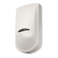
Caratteristiche
• Sensore volumetrico da interno a doppia tecnologia in cui il rilevamento dell’infrarosso è basato su PIR Tecnologia Quad per analizzare
più accuratamente le dimensioni corporee di animali no a 25 Kg di peso e il rilevamento della microonda è basato su concetto Doppler.
• Regolazioni separate sensibilità infrarosso e microonda.
• Collegamenti tramite contatti a relè con resistenze di bilanciamento integrate, per allarme e tamper, di vari valori selezionabili.
Prima alimentazione
Il sensore rimane in blocco per circa 60 secondi, durante i quali i led lampeggiano.
Modalità di funzionamento
• AND: In questa modalità il sensore attiva il relè di allarme ed il led blu solo quando entrambe le tecnologie andranno in allarme.
• SECURITY: In questa modalità il sensore attiva il relè di allarme ed il led blu anche in corrispondenza di un singolo allarme del solo
infrarosso o di una serie di allarmi consecutivi della sola microonda.
Copertura (FIG. A)
Con lente in dotazione: apertura 90°, portata di 15 metri con altezza di installazione a 2,2 metri da terra.
Con lente opzionale (Mod. CLI): apertura 5°, portata di 15 metri con altezza di installazione a 2,2 metri da terra.
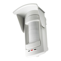
Installazione dello snodo opzionale mod. K21 e dello snodo con antistrappo opzionale mod. K21T (FIG. C)
A parete: assemblare e ssare, con la vite (8) e il dado (2), i pezzi (1, 9, 6) che compongono lo snodo, al fondo del sensore (7).
A softto: assemblare e ssare, con la vite (8) e il dado (2), i pezzi (1, 4, 6) che compongono lo snodo, al fondo del sensore (7).
Per entrambi gli snodi, posizionare il modulo Antistrappo (3) come riportato in FIG. C.
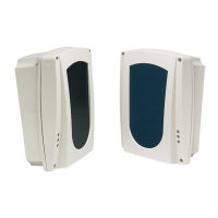
Cambio lente opzionale mod. CLI (FIG. D)
Dall’interno del coperchio, sganciare i due fermi (12) posti ai lati della lente installata (13), inserire il convogliatore (14) e poi la lente mod. CLI.
Morsettiera (FIG. B)
- Negativo di alimentazione 12 V =
+ Positivo di alimentazione 12 V =
LED Chiudendo a positivo questo morsetto, si attiva il funzionamento dei led anche se esclusi con DIP 1 in OFF.
ALARM
C / NC
Uscita di segnalazione di Allarme. Contatto normalmente chiuso (vedi jumper ALARM nella tabella E)
NOTA: se il jumper S1 è in posizione 2 (vedi tabella E), questo contatto risulta in serie a quello di TAMPER
TEOL Non usato
TAMPER
C / NC
Uscita di segnalazione di Tamper. Contatto normalmente chiuso (vedi jumper TAMPER nella tabella E)
NOTA: se il jumper S1 è in posizione 2 (vedi tabella E), questo contatto risulta in serie a quello di ALLARME
Resistenze di bilanciamento (Tabella E)
Le uscite ALARM e TAMPER possono essere congurate C/NC oppure con delle resistenze di bilanciamento in parallelo. Inoltre possono
essere separate o collegate in serie internamente. Vedi le varie congurazioni nella Tabella E.
Trimmer (FIG. B)
• MW ADJ: regolazione portata microonda. Aumenta in senso orario.
• PIR ADJ: regolazione portata infrarosso. Aumenta in senso orario.
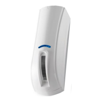
LED (FIG. B)
• LED BLU: Spento con sensore a riposo. Lampeggia per 60 secondi alla prima alimentazione. Acceso sso con sensore in allarme.
• LED VERDE: Spento con PIR a riposo. Lampeggia per 60 secondi alla prima alimentazione. Acceso sso con PIR in allarme.
• LED GIALLO: Spento con MW a riposo. Lampeggia per 60 secondi alla prima alimentazione. Acceso sso con MW in allarme.
Dip Switch (FIG. B)
LED
(L)
DIP 1 ON Default I led seguono il funzionamento descritto nel capitolo LED
DIP 1 OFF I led risultano disabilitati. Vedi funzionamento con ingresso LED chiuso a positivo.
IMPULSI IP
(P)
DIP 2 ON L’infrarosso genera allarme con 1 impulso
DIP 2 OFF Default L’infrarosso genera allarme con 2 impulsi
SENSIBILITA’ MW
(M)
DIP 3 ON Sensibilità alta della microonda
DIP 3 OFF Default Sensibilità default della microonda
PET IMMUNITY
(W1) e (W2)
DIP 4 ON
DIP 5 OFF
Immunità agli animali no a 25 Kg di peso.
DIP 4 OFF
DIP 5 ON
Immunità agli animali no a 12 Kg di peso.
DIP 4 ON
DIP 5 ON
Default Immunità agli animali 0 Kg (ESCLUSA).
AND / SECURITY
(A)
DIP 6 ON Funzionamento in modalità SECURITY
DIP 6 OFF Default Funzionamento in modalità AND
Caratteristiche tecniche
Tensione nominale 12 V =
Tensione di alimentazione Max: 15 V = / Min: 10,5 V =
Assorbimento 38 mA in quiete / 42 mA in allarme
Copertura Con lente in dotazione: 90° su 15 metri effettivi
Con lente opzionale (mod. CLI): 5° su 15 metri effettivi
Frequenza microonda 10,525 Gh
Segnale emesso dalla microonda Impulsato
Altezza installazione 2,2 metri da terra
Condizioni funzionamento scheda elettronica 0° C / +50° C
Peso (grammi) 110
Dimensioni (millimetri) (PxLxH) 39 x 65 x 120
Dichiarazione di Conformità
Con la presente AVS Electronics S.p.A. dichiara che Jet DT è conforme ai requisiti essenziali e alle altre disposizioni rilevanti stabilite dalla
direttiva 1999/05/EC (R&TTE) e alla Norma Europea EN50131-2-4 GRADO 2 CLASSE II.
La dichiarazione di conformità può essere consultata nell’area riservata del sito AVS Electronics.com.
L’alimentazione deve provenire da un circuito a bassissima tensione di sicurezza ed avente le caratteristiche di una sorgente a
potenza limitata protetta da fusibile.
INSTALLAZIONE E MANUTENZIONE DEVONO ESSERE FATTE DA PERSONALE QUALIFICATO
AVS ELECTRONICS S.p.a. si riserva il diritto di apportare modiche in qualsiasi momento e senza preavviso.
JET DT
90°
5°
5°
MW
PIR
A
B
1
2
3
4
5
6
7
8
9
10
10
11
6
7
8
5
1
2
1
2
3
9
10
10
C
E
10 kohm
4,7 kohm
2,2 kohm
1 kohm
N.C.
ALARM
ALARM
ALARM
ALARM
TAMPER
TAMPER
TAMPER
TAMPER
ALARM TAMPER
S1
-
+
12V DC
LED NC C TEOL NC C
ALARM TAMPER
-
+
12V DC
LED NC C TEOL NC C
ALARM TAMPER
S1
1
2
X X
1m 2m 3m 4m 5m 6m 7m 8m 9m 10m 11m 12m
2,2m
13m 14m 15m
ENGLISH
Features
• Dual technology internal infrared volumetric sensor based on PIR Quad Technology for precise analysis of the body dimensions of
pets weighing up to 25 kg and Doppler microwave motion sensor technology.
• Independent adjustment of infrared and microwave sensitivity.
• Connections with relay contacts with built-in balancing resistors for various alarm and tamper value.
Initial start-up
The sensor is kept on standby for about 60 seconds, during which time the LEDs blink.
Operating mode
• AND: In this mode, the sensor activates the alarm relay and blue LED only when both the technologies enter alarm mode.
• SECURITY: In this mode, the sensor activates the alarm relay and the blue LED also when the infrared technology triggers a single
alarm or the microwave technology triggers a series of consecutive alarms.
Cover (FIG. A)
With the lens provided: opening span 90°, capacity for 15 metres with height of installation at 2.2 metres above the ground.
With the optional lens (Mod. CLI): opening span 5°, capacity for 15 metres with height of installation at 2.2 metres above the ground.
Installation of the mod. K21 optional support and mod. K21T support with optional anti-tamper device (FIG. C)
Wall-mounted: use the screw (8) and nut (2) to secure the parts (1, 9, 6) of the support to the base of the sensor (7).
Ceiling-mounted: use the screw (8) and nut (2) to secure the parts (1, 4, 6) of the support to the base of the sensor (7).
In the case of both the supports, install the anti-tamper module (3) as shown in FIG. C.
Replacing the mod. CLI optional lens (FIG. D)
Release the two clips (12) either side of the lens (13) from inside the cover, apply the window narrower (14) and the curtain lens mod. CLI.
Terminal block (FIG. B)
- Negative power supply 12 V =
+ Positive power supply 12 V =
LED With this terminal positively closed, the LEDs are enabled even if they are excluded with the DIP 1 OFF.
ALARM
C / NC
Alarm signal output. Normally closed contact (refer to the ALARM jumper in table E)
NOTE: if jumper S1 is in position 2 (refer to table E), this contact is in series with the TAMPER one
TEOL Not used
TAMPER
C / NC
Tamper signal output. Normally closed contact (refer to the TAMPER jumper in table E)
NOTE: if jumper S1 is in position 2 (refer to table E), this contact is in series with the ALARM one
Balancing resistors (Table E)
The ALARM and TAMPER outputs can be congured as C/NC or with balancing resistors in parallel. They can also be separated or con-
nected in series internally. Refer to the various congurations in Table E
Trimmer (FIG. B)
• MW ADJ: microwave capacity adjustment. Turn clockwise to increase.
• PIR ADJ: infrared capacity adjustment. Turn clockwise to increase.
LED (FIG. B)
• BLUE LED: Off with sensor on standby. Blinks for 60 seconds during initial start-up. Steady with the sensor in alarm mode.
• GREEN LED: Off with PIR on standby. Blinks for 60 seconds during initial start-up. Steady with PIR in alarm mode.
• YELLOW LED: Off with MW on standby. Blinks for 60 seconds during initial start-up. Steady with MW in alarm mode.
Dip Switch (FIG. B)
LED
(L)
DIP 1 ON Default The LEDs operate in the manner described in the chapter LED
DIP 1 OFF The LEDs are disabled. Refer to operation with the LED input positively closed.
IMPULSI IP
(P)
DIP 2 ON The infrared technology generates an alarm with 1 pulse
DIP 2 OFF Default The infrared technology generates an alarm with 2 pulses
SENSIBILITA’ MW
(M)
DIP 3 ON Microwave high sensitivity
DIP 3 OFF Default Microwave default sensitivity
PET IMMUNITY
(W1) e (W2)
DIP 4 ON
DIP 5 OFF
Pet immunity up to 25 Kg in weight.
DIP 4 OFF
DIP 5 ON
Pet immunity up to 12 Kg in weight.
DIP 4 ON
DIP 5 ON
Default Pet immunity 0 Kg (EXCLUDED).
AND / SECURITY
(A)
DIP 6 ON Operation in SECURITY mode
DIP 6 OFF Default Operation in AND mode
Technical Features
Rated voltage 12 V =
Power supply Max: 15 V = / Min: 10.5 V =
Absorption 38 mA idle / 42 mA in alarm mode
Coverage area With the lens provided: 90° effectively for 15 metres
With the optional lens (mod. CLI: 5° effectively for 15 metres
Microwave frequency 10.525 Gh
Microwave signal Pulsed
Height of installation 2.2 metres above the ground
Operating conditions of the printed circuit board 0° C / +50° C
Weight (grams) 110
Dimensions (millimetres) (WxLxH) 39 x 65 x 120
Declaration of Conformity
AVS Electronics S.p.A. hereby declares that Jet DT is in compliance with the essential requirements and the other relevant provisions set
out in directive 1999/05/EC (R&TTE) and in compliance with the European Standard EN50131-2-4 Grade 2 Class II.
The declaration of conformity is available for reference in the reserved area of the site AVS Electronics.com.
The power supply must come from a very low voltage security circuit with the features of a limited power source protected by
a fuse.
INSTALLATION AND MAINTENANCE MUST BE CARRIED OUT BY QUALIFIED PERSONNEL.
AVS ELECTRONICS S.p.a. reserves the right to make changes at any time without prior notice.
D
12
13
14
22.0000