Do you have a question about the AVS Electronics BF100 R and is the answer not in the manual?
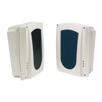
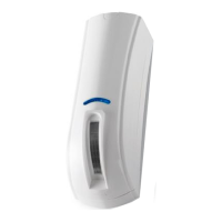
Describes the emitter and receiver system using a reflecting panel for smoke detection.
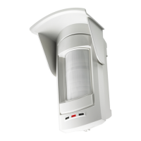
Covers view-finder, Led/display module for calibration, and automatic self-calibration.
Details alarm/fault outputs and serial interface for remote panel connection.
Explains the purpose of specific terminals for alarm, fault, and output connections.
Details the function of LEDs for signal visualization and detector condition.
Describes the purpose and configuration of jumpers S1 through S9 on the board.
Explains the function of dip switches 1 through 4 for mode and sensitivity settings.
Covers distances between beams, walls, ceiling, and roof inclination for proper installation.
Details reflector panel use, alignment, screw types, and maximum tolerance for mounting.
Guides through using view-finder, adjusters, and DIP switches for device calibration.
Explains sensitivity levels and DIP switch settings based on beam distance.
Describes LED status, alarm/fault signals, and BR100 module feedback in normal operation.
Details connecting beams to the BR100 panel and setting unique addresses for each.
Explains direct connection (OUT+F) and ALARM relay outputs to fire control units.
Lists key technical specifications including range, coverage, power, and approvals.
| Brand | AVS Electronics |
|---|---|
| Model | BF100 R |
| Category | Security Sensors |
| Language | English |