Curtarolo (Padova) Italy
www.avselectronics.com
ist0922V1.2
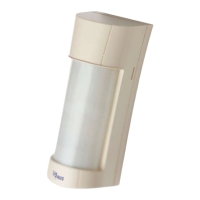
SPECTRUM PA WALL
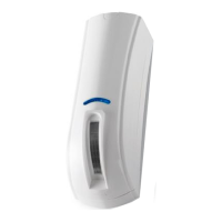
SPECTRUM PA WALL AM
D
A
1,8 m
0
1
10m 10m
5m5m
10°
1,2 m
0m 1m 2m 3m
4m 5m
6m
7m
8m 9m 10m 11m 12m1m12m 11m 10m 9m 8m
7m
6m
5m 4m
3m 2m
Caratteristiche
- E’ un rilevatore volumetrico di movimento, con collegamento lare, composto da un doppio infrarosso, ideato per la protezione sia
interna che esterna.
- E’ progettato per la protezione di aree esterne e per ridurre al minimo il rischio di falsi allarmi dovuti a condizioni meteorologiche, elementi
ambientali, animali in libertà, ecc...
- E’ dotato di un buzzer e di led per dare una segnalazione ottico-acustica (Walk Test).
- E’ dotato di:
• Compensazione termica, il sensore compensa automaticamente la portata al variare della temperatura ambiente, ciò nonostante
la resa del sensore può variare sensibilmente in funzione di particolari intervalli di temperature.
• Filtri di protezione contro la luce bianca e quella solare, per ottimizzare la lettura degli infrarossi
• Accelerometro (solo Mod. Spectrum PA WALL AM), per la segnalazione dello strappo e disorientamento (non rileva la vibrazione).
Una eventuale rimozione non autorizzata viene segnalata dal sensore come TAMPER.
• Antimascheramento infrarosso (solo Mod. Spectrum PA WALL AM), formato da un ricevitore RX e due trasmettitori TX ad
infrarossi attivi su entrambi i lati, che rilevano gli ostacoli posti di fronte al sensore no ad una distanza di circa 7 cm. La calibrazione
avviene alla chiusura del TAMPER (Contenitore e, se presente, Antistrappo) e dura circa 40 secondi, durante i quali il led Giallo
lampeggia lentamente. La segnalazione viene generata dopo circa 30 secondi dal rilevamento dell’ostacolo, durante i quali il led
Giallo lampeggia velocemente, se il sensore nel frattempo non genera un allarme. Durante la segnalazione di Antimascheramento,
il led Giallo è acceso sso. La segnalazione si resetta alla rimozione dell’ostacolo.
NOTA: Se il led GIALLO rimane acceso FISSO durante la fase di Calibrazione Antimask, indica che il sensore non riesce ad
effettuare correttamente la procedura a causa della luce solare che colpisce la lente, aprire e richiudere il TAMPER per ripetere la
procedura facendo ombra al sensore.
- E’ dotato di un ingresso ausiliario AUX (solo Mod. Spectrum PA WALL AM) per gestire un ulteriore ingresso di allarme o il circuito di
antistrappo del sensore stesso
- E’ dotato di Mascherine Adesive Oscuranti per mascherare uno dei due lati.
- Può essere dotato di una TETTOIA protettiva opzionale (Mod. SSC PROTEZIONE FRONT)
Installazione
Per l’apertura e l’installazione del sensore vedi le illustrazioni stampate nella parte interna della confezione.
Caratteristiche tecniche
Tensione nominale 12 V =
Tensione di alimentazione Max: 15 V = / Min: 10,5 V =
Assorbimento 25 mA in quiete / 31 mA in allarme
Copertura 10° su 12 metri effettivi nei due lati opposti
Antimascheramento infrarosso sì (solo Mod. Spectrum PA WALL AM)
Altezza installazione da 1,2 metri da terra
Condizioni funzionamento scheda elettronica -25° C / +55° C
Peso (grammi) 260
Dimensioni senza TETTOIA (millimetri) (PxLxH)
Dimensioni con TETTOIA (millimetri) (PxLxH)
68,3 x 75,4 x 189,4
87,3 x 75,4 x 189,4
Grado di protezione IP55
Prima alimentazione
Il sensore rimane in blocco per circa 60 secondi, durante i quali i led lampeggiano.
Modalità di funzionamento
Il sensore attiva il relè di allarme ed il led blu quando uno dei sensori disposti sui due lati opposti andrà in allarme.
Portata Infrarosso (vedi FIG. F dettaglio 1)
- Installazione da 1,2 a 1,5 metri dal terreno (FIG. B): è possibile modicare la portata dell’infrarosso da 12 a 3 metri variando l’altezza
del PIR inferiore da 1 a 5.
Per variare l’altezza del PIR è necessario allentare la Vite 1 in FIG. D. Rissarla per bloccare il PIR nella posizione desiderata.
NOTA: La regolazione ottimale della portata, si ha installando il sensore perpendicolarmente al terreno.
Copertura (FIG. A)
- La copertura è di 10° su entrambi i lati e la scheda elettronica deve essere ssata nella posizione orizzontale a 0° (vedi FIG. F dettaglio 2).
Morsettiera (FIG. B)
- Negativo di alimentazione 12 V =
+ Positivo di alimentazione 12 V =
C / NC Uscita di segnalazione Allarme. Contatto normalmente chiuso (vedi jumper ALARM nella tabella E)
NOTA: se il jumper S1 è in posizione 2 (vedi tabella E), questo contatto risulta in serie a quello di TAMPER
AM AM Uscita di segnalazione Antimascheramento (solo Mod. Spectrum PA WALL AM).
Contatto normalmente chiuso (vedi jumper ANTIMASK nella tabella E)
T T Uscita di segnalazione di Tamper. Contatto normalmente chiuso (vedi jumper TAMPER nella tabella E)
NOTA: se il jumper S1 è in posizione 2 (vedi tabella E), questo contatto risulta in serie a quello di ALLARME
B Ingresso che permette al sensore di avere il riferimento dello stato della centrale. Per gestire questa informazione, a
centrale spenta questo ingresso deve risultare chiuso a positivo (solo Mod. Spectrum PA WALL AM).
In questa condizione il relè di allarme rimane chiuso, la microonda viene disalimentata e, nel caso di un allarme, il led ed
il buzzer non si attivano
AUX AUX è un ingresso con riferimento a negativo che attiva o il relè di Allarme o quello di Tamper (vedi DIP 5)
(solo Mod. Spectrum PA WALL AM)
Resistenze di bilanciamento (Tabella E)
Le uscite ALARM, TAMPER (tutti i modelli) e AM (
solo Mod. Spectrum PA WALL AM)
possono essere congurate C/NC (Jumper aperto)
oppure con delle resistenze di bilanciamento in parallelo (Jumper chiuso in base al valore di resistenza da impostare).
Inoltre possono essere separate o collegate in serie internamente.
Alcuni esempi di congurazioni sono riportati nella Tabella E:
1. I contatti di Allarme, Tamper e Antimask risultano indipendenti tra loro
2. I contatti di Allarme e di Tamper risultano in serie tra loro (è necessario inserire una delle 4 resistenze nel circuito Tamper). L’Antimask
è indipendente.
3. I contatti di Allarme e di Antimak risultano in serie tra loro. Il Tamper è indipendente.
4. I contatti di Allarme, Tamper e Antimask risultano in serie tra loro (è necessario inserire una delle 4 resistenze nel circuito Tamper).
LED (FIG. D)
- LED BLU: Spento con sensore a riposo. Lampeggia per 60 secondi alla prima alimentazione. Acceso sso con sensore in allarme.
- LED GIALLO
(solo Mod. Spectrum PA WALL AM)
: Spento a riposo. Lampeggia lento per 40 secondi durante la Calibrazione. Lampeggio
veloce per 30 secondi al rilevamento di un ostacolo. Acceso sso con Antimask in allarme.
Dip Switch (FIG. D)
Per accedere alla congurazione dei DIP SWITCH è necessario rimuovere lo SPECCHIO slandolo delicatamente verso l’alto (Vedi Fig. D dettaglio 3)
DIP 1 SENSIBILITÀ IR
ON Sensibilità dell’Infrarosso ridotta
Dichiarazione di Conformità
La dichiarazione di conformità può
essere consultata nell’area riservata
del sito AVS Electronics.com.
L’alimentazione deve provenire da
un circuito a bassissima tensione di
sicurezza ed avente le caratteristiche
di una sorgente a potenza limitata
protetta da fusibile.
INSTALLAZIONE E MANUTENZIO-
NE DEVONO ESSERE FATTE DA
PERSONALE QUALIFICATO
OFF Default Sensibilità dell’Infrarosso normale
DIP 2
INGRESSO AUX
(Abilitazione)
ON Gestione ingresso AUX abilitata
OFF Default Gestione ingresso AUX disabilitata
DIP 3
ANTIMASK
solo Mod. Spectrum PA WALL AM
ON Default Antimask abilitato
OFF Antimask escluso
DIP 4 ACCELEROMETRO
ON Default Accelerometro abilitato
OFF Accelerometro escluso
DIP 5
INGRESSO AUX
(Gestione)
ON Ingresso AUX attiva il relè di Allarme
OFF Default Ingresso AUX attiva il relè di Tamper
DIP 6 LED BLU
ON Default Led Blu abilitato
OFF Led Blu escluso
DIP 7
LED GIALLO
solo Mod. Spectrum PA WALL AM
ON Default Led Giallo abilitato
OFF Led Giallo escluso
DIP 8 BUZZER
ON Default Buzzer abilitato
OFF Buzzer escluso
In caso di installazioni su tetti di capannoni o edici in genere, particolarmente dove ci sono lucernari o altre superci riettenti o pavi-
mentazioni in asfalto che subiscono forte riscaldamento per l’irraggiamento del sole, si raccomanda usare la modalità a sensibilità ridotta
dell’infrarosso, in quanto, tali fattori, favoriscono l’insorgenza di falsi allarmi.
Tamper
- Il TAMPER antiapertura del coperchio è già installato e cablato di fabbrica.
- Il TAMPER antistrappo opzionale da installare sul fondo del sensore (Cod.1135112) è consigliato il collegamento tra i morsetti AUX e - (negativo)
AVS ELECTRONICS S.p.a. si riserva il diritto di apportare modiche in qualsiasi momento e senza preavviso.
1
2
TAMP.
OK
F
45°
31°
18°
5°
0°
1 - 3 mt
2 - 5 mt
3 - 7 mt
4 - 9 mt
5 - 12 mt
1
2
B
IT ALIANO
ENGLISH
E
ALARM TAMPER ANTIMASK
10 KOHM
5,6 KOHM
4,7 KOHM
2,2 KOHM
N.C.
X
X
XX XX
XX
1
2
3
4
ALLARM
ANTIMASK
S1
S2
1 2 3 4 1 2 3 4 1 2 3 4
1 2 3
+-
C NC
AM
T T B
AUX
AM
LD1
LD2
1 2 3
4
5
6
7
8
ON
1
2
3
4
5
TAMPER
S2
1 2 3 4 1 2 3 4 1 2 3 4
1 2 3
+-
C NC
AM
T T B
AUX
AM
LD1
LD2
1 2 3
4
5
6
7
8
ON
1
2
3
4
5
TAMPER
ALLARM
ANTIMASK
S1
S2
1 2 3 4 1 2 3 4 1 2 3 4
1 2 3
+-
C NC
AM
T T B
AUX
AM
LD1
LD2
1 2 3
4
5
6
7
8
ON
1
2
3
4
5
TAMPER
ALLARM
ANTIMASK
S1
S2
1 2 3 4 1 2 3 4 1 2 3 4
1 2 3
+-
C NC
AM
AUX
AM
LD1
LD2
1 2 3
4
5
6
7
8
ON
1
2
3
4
5
TAMPER
ALLARM
ANTIMASK
S1
S2
1 2 3 4 1 2 3 4 1 2 3 4
1 2 3
+-
C NC
AM
T T B
AUX
AM
LD1
LD2
1 2 3
4
5
6
7
8
ON
1
2
3
4
5
TAMPER
ALLARM
ANTIMASK
S1
S2
1 2 3 4 1 2 3 4 1 2 3 4
1 2 3
+-
C NC
AM
T T B
AUX
AM
LD1
LD2
1 2 3
4
5
6
7
8
ON
1
2
3
4
5
TAMPER
TAMPER
ALLARM
ANTIMASK
S1
S2
1 2 3 4 1 2 3 4 1 2 3 4
1 2 3
+-
C NC
AM
T T B
AUX
AM
LD1
LD2
1 2 3
4
5
6
7
8
ON
1
2
3
4
5
TAMPER
ALLARM
ANTIMASK
S1
S2
1 2 3 4 1 2 3 4 1 2 3 4
1 2 3
+-
C NC
AM
T T B
AUX
AM
LD1
LD2
1 2 3
4
5
6
7
8
ON
1
2
3
4
5
TAMPER
ALLARM
ANTIMASK
S1
S2
1 2 3 4 1 2 3 4 1 2 3 4
1 2 3
+-
C NC
AM
T T B
AUX
AM
LD1
LD2
1 2 3
4
5
6
7
8
ON
1
2
3
4
5
TAMPER
S2
1 2 3 4 1 2 3 4 1 2 3 4
1 2 3
+-
C NC
AM
T T B
AUX
AM
LD1
LD2
1 2 3
4
5
6
7
8
ON
1
2
3
4
5
TAMPER
ALARM
TAMPER
ALLARM
ANTIMASK
S1
S2
1 2 3 4 1 2 3 4 1 2 3 4
1 2 3
+-
C NC
AM
T T B
AUX
AM
LD1
LD2
1 2 3
4
5
6
7
8
ON
1
2
3
4
5
TAMPER
ALLARM
ANTIMASK
S1
S2
1 2 3 4 1 2 3 4 1 2 3 4
1 2 3
+-
C NC
AM
T T B
AUX
AM
LD1
LD2
1 2 3
4
5
6
7
8
ON
1
2
3
4
5
TAMPER
ALLARM
ANTIMASK
S1
S2
1 2 3 4 1 2 3 4 1 2 3 4
1 2 3
+-
C NC
AM
T T B
AUX
AM
LD1
LD2
1 2 3
4
5
6
7
8
ON
1
2
3
4
5
TAMPER
ALLARM
ANTIMASK
S1
S2
1 2 3 4 1 2 3 4 1 2 3 4
1 2 3
+-
C NC
AM
T T B
AUX
AM
LD1
LD2
1 2 3
4
5
6
7
8
ON
1
2
3
4
5
TAMPER
ALARM
ANTIMASK
ALLARM
ANTIMASK
S1
S2
1 2 3 4 1 2 3 4 1 2 3 4
1 2 3
+-
C NC
AM
T T B
AUX
AM
LD1
LD2
1 2 3
4
5
6
7
8
ON
1
2
3
4
5
TAMPER
ALLARM
ANTIMASK
S1
S2
1 2 3 4 1 2 3 4 1 2 3 4
1 2 3
+-
C NC
AM
T T B
AUX
AM
LD1
LD2
1 2 3
4
5
6
7
8
ON
1
2
3
4
5
TAMPER
ALLARM
ANTIMASK
S1
S2
1 2 3 4 1 2 3 4 1 2 3 4
1 2 3
+-
C NC
AM
T T B
AUX
AM
LD1
LD2
1 2 3
4
5
6
7
8
ON
1
2
3
4
5
TAMPER
ALLARM
ANTIMASK
S1
S2
1 2 3 4 1 2 3 4 1 2 3 4
1 2 3
+-
C NC
AM
T T B
AUX
AM
LD1
LD2
1 2 3
4
5
6
7
8
ON
1
2
3
4
5
TAMPER
TAMPER
Features
- It is a wired volumetric motion detector with dual infrared sensor designed for both internal and external protection.
- Sensor designed for the protection of outdoor areas and the minimisation of the risk of false alarms due to weather conditions, environ-
mental elements, animals, etc
- It has a buzzer and LED for the optical and sound alarm signalling function (Walk Test).
- It is equipped with:
• Thermal compensation, whereby the sensor automatically adjusts the performance of the system to compensate for changes in
ambient temperature. Its own performance can, however, vary considerably in relation to particular temperature ranges.
• White light and solar lters to optimise performance of the infrared sensors
• Accelerometer (
only Mod. Spectrum PA WALL AM)
that indicates tampering (does not detect vibration). The sensor indicates unau-
thorised removal as a TAMPER event.
• Anti-masking with infrared (
only Mod. Spectrum PA WALL AM)
, comprising an RX receiver and two TX transmitter with active
infrared on both sides, that detect obstacles at a distance of about 7 cm in front of the sensor. Calibration occurs after closing of the
TAMPER device (Container and Anti-tear device, when applicable) and takes about 40 seconds, during which time the yellow LED
ashes slowly. The presence of an obstacle is indicated about 30 seconds after it is detected, during which time the yellow LED
ashes quickly if the sensor does not generate an alarm in the meantime. The yellow LED remains steady during the anti-masking
signal. Removing the obstacle stops the signal.
NOTE: if the YELLOW LED remains on and STEADY during the Antimask Calibration phase, this means the sensor is unable
to complete the procedure properly due to the reection of light on the lens. Open and close the TAMPER to repeat the procedure,
shading the sensor.
- It has an AUX auxiliary input (only Mod. Spectrum PA WALL AM) for managing another alarm input or the anti-tear circuit of the same sensor
- It has Adhesive Masks for to mask one of the two sides.
- It can be equipped with an optional protective ROOF (Mod. SSC FRONT PROTECTION)
Installation
For opening and installation of the sensor see the illustrations printed on the inside of the package.
Technical Features
Rated voltage 12 V =
Power supply Max: 15 V = / Min: 10,5 V =
Absorption 25 mA idle / 31 mA in alarm mode
Coverage 10° effectively for 12 metres in the two opposite sides
Anti-masking with infrared yes (
only Mod. Spectrum PA WALL AM)
Height of installation 1.2 metres above the ground
Operating conditions of the printed circuit board -25° C / +55° C
Weight (grams) 260
Dimensions without ROOF (millimetres) (WxLxH)
Dimensions with ROOF (millimetres) (WxLxH)
68,3 x 75,4 x 189,4
87,3 x 75,4 x 189,4
Degree of protection IP55
Initial start-up
The sensor is kept on standby for about 60 seconds, during which time the LEDs blink.
Operating mode
The sensor activates the alarm relay and the blue LED when one of the sensors arranged on opposite sides enter alarm mode
Infrared capacity (see FIG. F detail 1)
- Installation 1.2 to 1.5 metres above the ground (FIG. B): it is possible to change infrared capacity from 12 to 3 metres by changing the
height of the lower PIR from 1 to 5.
To change the height of the PIR, loosen Screw 1 in FIG. D. Refasten it to lock the PIR in the required position.
NOTE: The sensor should ideally be installed perpendicular with the ground for optimal adjustment of capacity.
Coverage (FIG. A)
- The coverage is of 10° on both sides. The printed circuit board must be locked in the horizontal position at 0° (see FIG. F detail 2).
Terminal block (FIG. B)
- Negative power supply 12 V =
+ Positive power supply 12 V =
C / NC Alarm signal output. Normally closed contact (refer to the ALARM jumper in table E)
NOTE: if jumper S1 is in position 2 (refer to table E), this contact is in series with the TAMPER one
AM AM
Antimask signalling output (only Mod. Spectrum PA WALL AM). Normally closed contact (refer to the ANTIMASK jumper in table E)
T T Tamper signal output. Normally closed contact (refer to the TAMPER jumper in table E)
NOTE: if jumper S1 is in position 2 (refer to table E), this contact is in series with the ALARM one
B
Input that allows the sensor to obtain the status reference of the central control unit. In order to manage this information, this input
must be positively closed when the central control unit is turned off (only Mod. Spectrum PA WALL AM).
In this condition, the alarm relay is closed, the microwave is off and, in the case of an alarm, the LED and buzzer are not activated
AUX AUX is an input with negative reference that activates either the Alarm relay or the Tamper relay (see DIP 5)
(
only Mod. Spectrum PA WALL AM)
Balancing resistors (Table E)
The ALARM, TAMPER (all type) and ANTIMASK (
only Mod. Spectrum PA WALL AM)
outputs can be congured C/NC (Jumper open) or
with balancing resistors in parallel (Jumper closed on the basis of the resistance value to be set).
They can also be separated or connected in series internally.
Some examples of conguration are given in Table E:
Scheme 1. The Alarm, Tamper and Antimask contacts are independent of each other
Scheme 2. The Alarm and Tamper contacts are in series with each other (one of the 4 resistors must be inserted on the Tamper circuit).
The Antimask contact is independent.
Scheme 3. The Alarm and Antimask contacts are in series with each other. The Tamper contact is independent.
Scheme 4. The Alarm, Tamper and Antimask contacts are in series with each other (one of the 4 resistors must be inserted on the Tamper circuit).
LED (FIG. D)
- BLUE LED: Off with sensor on standby. Blinks for 60 seconds during initial start-up. Steady with the sensor in alarm mode.
- YELLOW LED (
only Mod. Spectrum PA WALL AM
): Off at standby. Flashes slowly for 40 seconds during Calibration. Flashes quickly
for 30 seconds during detection of an obstacle. Steady with Antimask in alarm mode
Dip Switch (FIG. D)
To access the DIP SWITCHES it is necessary to remove the mirror sliding it carefully upward (See Fig. D detail 3)
DIP 1 IR SENSITIVITY
ON Reduced infrared sensitivity
Declaration of Conformity
The declaration of conformity
is available for reference in the
reserved area of the site
AVS Electronics.com.
The power supply must come
from a very low voltage security
circuit with the features of a
limited power source protected
by a fuse.
INSTALLATION AND MAIN-
TENANCE MUST BE
CARRIED OUT BY
QUALIFIED PERSONNEL
OFF Default Normal infrared sensitivity
DIP 2
AUX INPUT
(Enabling)
ON Management of AUX input enabled
OFF Default Management of AUX input disabled
DIP 3
ANTIMASK
only Mod. Spectrum PA WALL AM
ON Default Antimask enabled
OFF Antimask disabled
DIP 4 ACCELEROMETER
ON Default Accelerometer enabled
OFF Accelerometer disabled
DIP 5
AUX INPUT
(Management)
ON The AUX input enables the Alarm relay
OFF Default The AUX input enables the Tamper relay
DIP 6 BLUE LED
ON Default Blue led enabled
OFF Blue led disabled
DIP 7
YELLOW LED
only Mod. Spectrum PA WALL AM
ON Default Yellow LED enabled
OFF Yellow LED disabled
DIP 8 BUZZER
ON Default Buzzer enabled
OFF Buzzer disabled
In case of roof installations in industrial or civil buildings in general, especially if skylights or other reective surfaces are present, and/
or asphaltic coated grounds showing strong heating by sun irradiation exist, it is recommended to set the reduced sensitivity mode of the
infrared, because those factors favor the insurgence of false alarms.
Tamper
- The anti-opening TAMPER device of the cover is installed and wired at the factory.
- The optional anti-tear TAMPER device is to be installed at the base of the sensor (Code 1135112) and it is advisable to make the con-
nection between the AUX and - (negative) terminals
AVS ELECTRONICS S.p.a. reserves the right to make changes at any time without prior notice
3
TAMPER ALLARM
ANTIMASK
S1
S2
1 2 3 4 1 2 3
4 1 2
3 4
1 2 3
+-
C NC
AM
T T B
AUX
AM
1
2
3
4
5