Do you have a question about the AVS Electronics OUTSPIDER DT and is the answer not in the manual?
Describes the sensor's behavior upon first power application, including LED and buzzer activity.
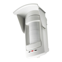
Explains the sensor's design for outdoor use and its advanced signal analysis compared to conventional sensors.
Details how the infrared and microwave sections operate and trigger an alarm in default mode.
Explains different sensitivity settings for infrared and directional modes for microwave.
Describes two alarm logic modes: AND (both technologies must trigger) and SECURITY (repeated single triggers).
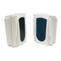
Explains how to attach the sensor base to a metal plate using stops and screws.
Describes attaching the sensor base to a joint, noting when not to use the metal plate.
Lists the functions configurable via DIP Switch SW2, such as connection mode, buzzer, and LED behavior.
Shows the default factory settings for the DIP switches on SW2 for sensor configuration.
Details the different sensitivity levels (Default, Low, Medium, High) for the infrared detection.
Describes microwave operation modes (Default, Approaching, Moving Away, No Control) for the OutSpider DT.
Explains the AND and SECURITY modes for alarm generation in OutSpider DT.
Describes the anti-masking circuit, its operation, and the detection of dirty lenses, including LED indications.
Lists various diagnostic checks available through the software, such as signal charts and output status.
Details the configurable parameters and functions like sensitivity, operational modes, and firmware updates.
Details the procedure for connecting the sensor directly or remotely via USB using the OUTUSB adapter or satellite.
Describes how to establish a remote connection using a modem through PSTN or GSM lines via the XSATHP satellite.
Explains the importance of synchronizing the sensor's date and time with the PC for event history logging.
Highlights key parameters displayed for sensor status, such as temperature, compensation, and power supply.
Describes the meaning of LED colors (green to red) indicating the status of Alarm, Tamper, Aux, Antimask, Lenses, and Microwave.
Shows the interface for configuring OutSpider DT parameters, including sensitivity, microwave mode, and alarm options.
Shows the interface for configuring OutSpider PA parameters, including sensitivity, antimask, and alarm memory.
Explains the function of the REC and STOP buttons for recording sensor signals to the PC for analysis.
Details how to interpret the red and white lines representing infrared signals and their correlation for alarm triggering.
Explains the yellow line representing the microwave signal and its relation to movement detection and security mode.
Describes the green line representing the anti-masking circuit's signal, indicating normal operation or detection of obstacles.
Shows combined infrared and microwave signals, illustrating background noise and useful movement detection.
Details the steps to load alarm event data from the sensor to the PC via HPWIN software.
Guides on how to display specific alarm events, showing signal waveforms and associated parameters like temperature and power.
Explains how to navigate the recordings archive to select and load specific signal files for analysis.
| Brand | AVS Electronics |
|---|---|
| Model | OUTSPIDER DT |
| Category | Security Sensors |
| Language | English |