- 35 -
LED
Yellow Steady:
Fast flashing:
Slow flashing:
Flashing:
Passive infrared alarm
signal
Antimask alarm signal
Dirty lenses fault signal
Alternately with red LED for
about 60 seconds at first
feeding
Red Steady:
Flashing:
General alarm signal
Alternately with yellow LED
for about 60 seconds at
first feeding
Green Steady: Microwave section alarm
signal
Trimmer for
adjusting
microwave capacity,
increases
when turned
clockwise
Buzzer for
alarm signalling
ON
123 4 56 7 8
ON
123 4 56 7 8
2.7
2.2
1.5
MW
1.0
SW1
SW2
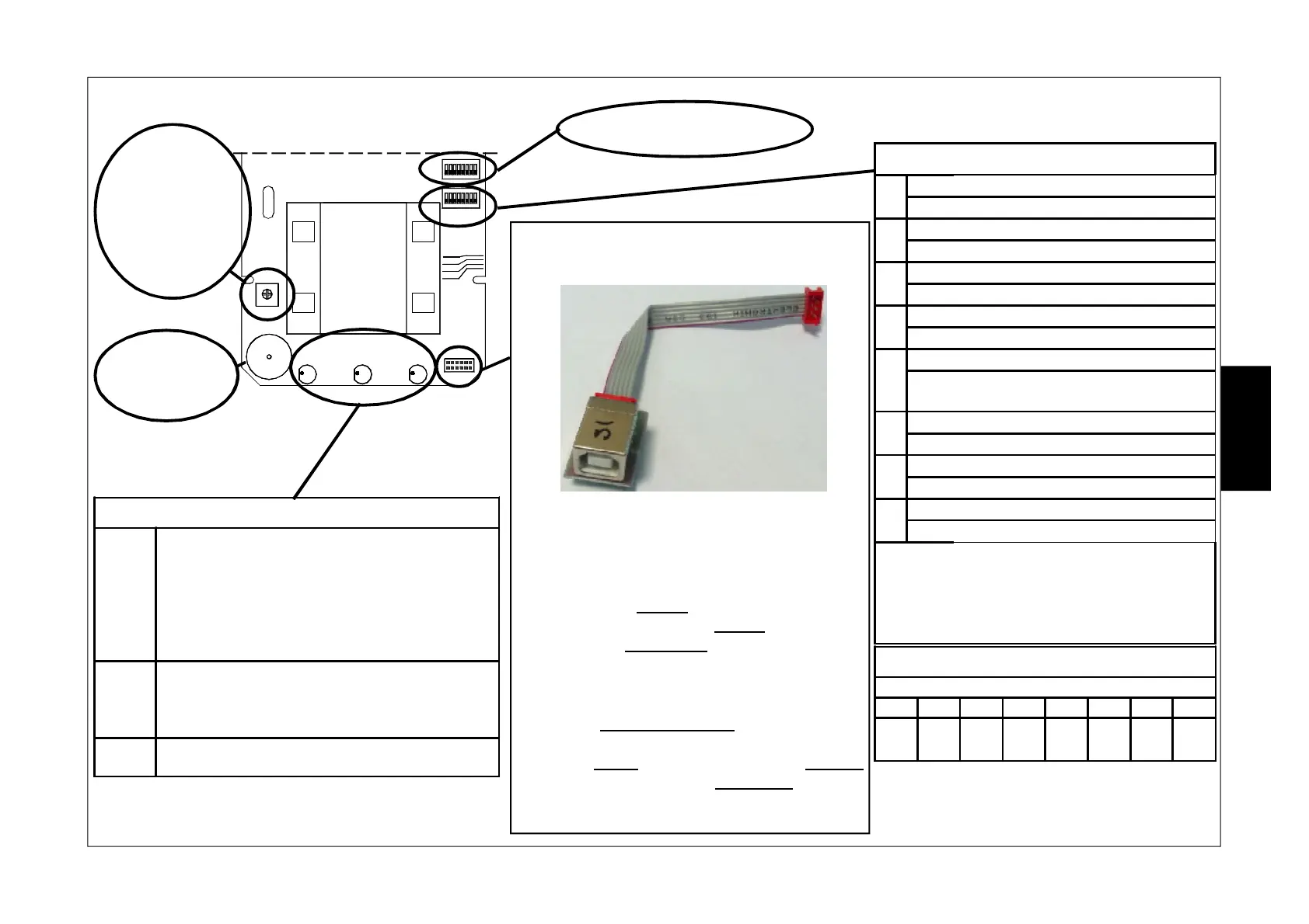
USB
GIALLO ROSSO VERDE
Connector for connecting the module mod.
USB-OUT (item 1135105) for direct handling of
the sensor by way of the PC.
With the USB-OUT adapter it is possible to
connect the sensor directly to the PC for managing
through the HPWIN software.
In the DIP/RELAY mode: through this connection
it is possible to display the configuration made
by way of the DIP SWITCH, display actual sensor
operation and acquire the download of the last
1920 events to the pc.
In PC/BUS mode: through this connection it is
possible to display and modify the configuration,
even is previously completed by way of DIP
SWITCH, adjust microwave sensitivity, display
actual sensor operation and acquire the download
of the last 1920 events to the pc.
SW 1: See next page
SW2 - FUNCTIONS
1
ON
Connection by DIP/RELAY
OFF
Connection by PC/BUS
2
ON
Buzzer enabled
OFF
Buzzer excluded
3
ON
Red LED enabled Alarm
OFF
Red LED excluded Alarm
4
ON
Green LED enabled Microwave
OFF
Green LED excluded Microwave
5
ON
Yellow LED enabled Antimask
OFF
Yellow LED excluded Antimask
and Dirty lenses
6
ON AUX input activates Alarm relay
OFF AUX input activates Tamper relay
7
ON Antimask function enabled
OFF Antimask function excluded
8
ON AUX input management enabled
OFF AUX input management disabled
IMPORTANT: In the mode withPC/BUS,
the functions configurable through DIP
SWITCH SW2 cannot be modified through
the PC except for the ANTIMASK function
(DIP 7)
DEFAULT
DIP SWITCH
1 2 3 4 5 6 7 8
ON ON ON ON ON OFF ON ON
E
N
G