- 33 -
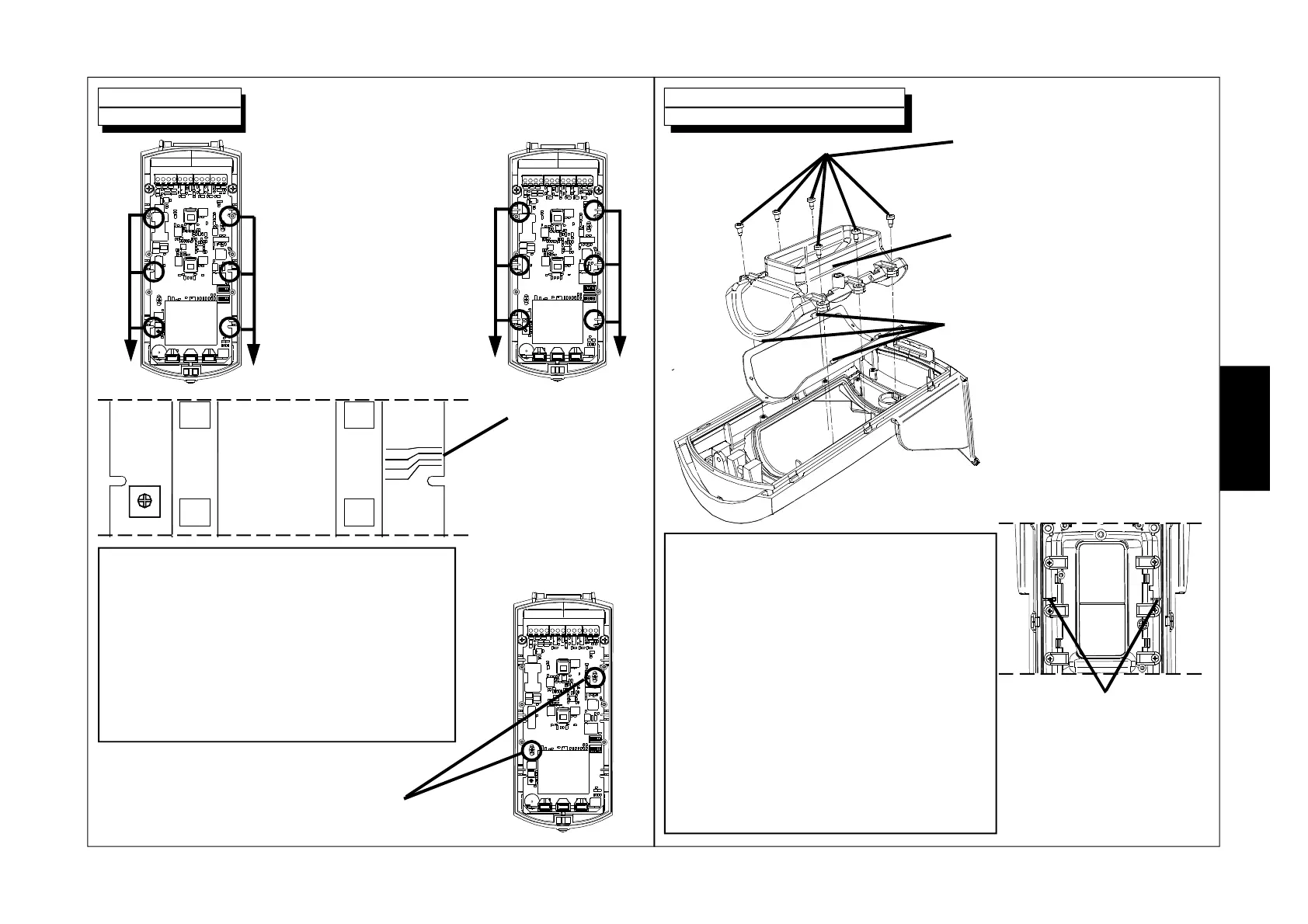
1. Insert the board until
the notches A coincide
with the stops B.
AA
2.7
2.2
1.5
MW
1.0
2. Slide the
board downward
until the pre-set
installation height is
reached.
BB
3. Fix the board once it is
positioned at the pre-set point.
1. Remove the 6 set screws.
2. Remove the lens support.
3. Unhook the lens from the
support by slightly pressing on the
four side stops.
4. Insert the selected lens
verifying that the four side
stops are in their seat.
6. Reposition the lens
support in its seat
verifying that the two
notches are correctly in
their guides.
5. Fix the 6 set screws once again
w With Wide angle lens (cod.FR09-0001-30):
opening 90°, capacity 15 m, recommended
installation height about 2.20 m.
w With Barrier lens (cod.FR09-0002-30):
opening 5°, capacity 15 m, recommended
installation height about 2.20 m.
w With Long range lens (cod.FR09-0003-30):
opening 5°, capacity 23 m, recommended
installation height about 2.20 m.
w With Animal alley lens (cod.FR09-0004-30):
opening 90°, capacity 15 m, recommended
installation height about 1.50 m.
The lens code is imprinted inside
a long side of the actual lens
NOTE: Due to the mechanical tolerances of the
various compo0nents it is possible that indicated
references relating to installation height are
slightly off.
IMPORTANT: For optimal coverage adjustment,
keep the board in proximity of the reference notch
for pre-set height and act on the joint to reach
suitable inclination.
E
N
G